ENFORCER VGA BALUN
Installation:
1.Make sure to use shielded twisted pair (STP) cable terminated with shielded
2.Since Cat 5 does not have sufficient lines to support VGA handshaking and control signals, it will be necessary to configure the monitor settings before installing the baluns:
To configure the monitor, connect it to the PC (or other video source), using a standard VGA cable. Configure the monitor (resolution, color depth, refresh rate, and so on) to the desired settings. Also, set the contrast and brightness levels to maximum. These will be adjusted after the VGA baluns are connected.
3.Turn off the power to the PC and monitor and disconnect the VGA cable.
4.Connect the PC side balun
5.Connect the monitor end balun
Note: For CRT monitors, a gender changer may be required. The
6.Connect a shielded Cat 5 cable to the
7.Make sure to tighten all the connections.
8.Turn on the PC and monitor.
9.Adjust the monitor contrast and brightness settings for comfortable viewing.
|
| ENFORCER VGA BALUN | |
|
|
|
|
|
|
|
|
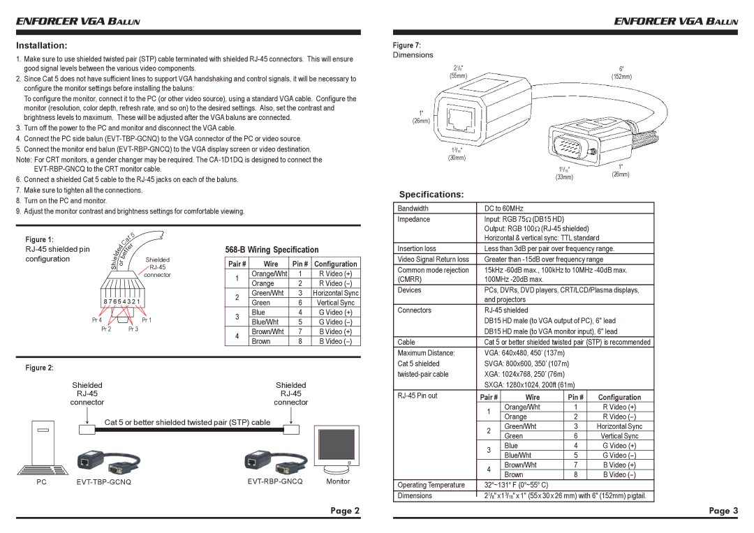
Figure 7: |
|
|
|
Dimensions |
|
|
|
21/8" |
| 6" |
|
(55mm) |
| (152mm) | |
1" |
|
|
|
(26mm) |
|
|
|
13/16" |
|
|
|
(30mm) |
|
|
|
| 15/16" | 1" |
|
| (33mm) | (26mm) | |
|
|
| |
Specifications: |
|
|
|
|
|
|
|
Bandwidth | DC to 60MHz |
|
|
Impedance | Input: RGB 75 (DB15 HD) |
|
|
| Output: RGB 100 |
|
|
Figure 1: |
|
|
|
|
|
|
|
|
| 5 |
| |
|
|
|
|
|
|
| a | |||||
|
|
|
|
|
| C | t | |||||
|
|
|
| d |
| r | ||||||
|
|
| e |
|
|
| e | |||||
|
| d |
|
| e | tt |
|
|
| |||
|
|
|
|
|
|
|
|
|
|
| ||
configuration |
|
| l |
|
|
|
|
|
|
| Shielded | |
| i r |
|
|
|
|
| ||||||
|
|
| e |
|
| b |
|
|
|
|
|
|
|
| h o |
|
|
|
|
| |||||
|
| S |
|
|
|
|
|
|
|
| ||
|
|
|
|
|
|
|
|
|
|
| connector | |
|
|
|
|
|
| |||||||
|
| 8 7 6 5 4 3 2 1 |
| |||||||||
|
|
|
|
|
|
|
|
|
|
|
|
|
| Pr 4 |
|
|
|
|
|
|
|
| Pr 1 | ||
|
|
|
|
|
|
|
|
| ||||
|
| Pr 2 |
|
|
|
|
|
| Pr 3 | |||
568-B Wiring Specification
Pair # | Wire | Pin # | Configuration | |
1 | Orange/Wht | 1 | R Video (+) | |
Orange | 2 | R Video | ||
| ||||
2 | Green/Wht | 3 | Horizontal Sync | |
Green | 6 | Vertical Sync | ||
| ||||
3 | Blue | 4 | G Video (+) | |
Blue/Wht | 5 | G Video | ||
| ||||
4 | Brown/Wht | 7 | B Video (+) | |
Brown | 8 | B Video | ||
|
| Horizontal & vertical sync: TTL standard |
Insertion loss | Less than 3dB per pair over frequency range. |
Video Signal Return loss | Greater than |
Common mode rejection | 15kHz |
(CMRR) | 100MHz |
Devices | PCs, DVRs, DVD players, CRT/LCD/Plasma displays, |
| and projectors |
Connectors | |
| DB15 HD male (to VGA output of PC), 6" lead |
| DB15 HD male (to VGA monitor input), 6" lead |
Cable | Cat 5 or better shielded twisted pair (STP) is recommended |
Maximum Distance: | VGA: 640x480, 450’ (137m) |
Cat 5 shielded | SVGA: 800x600, 350’ (107m) |
Figure 2:
Shielded | Shielded | ||||||
connector | connector | ||||||
|
|
|
| Cat 5 or better shielded twisted pair (STP) cable |
|
|
|
|
|
|
|
|
|
| |
|
|
|
|
|
|
|
|
|
|
|
|
|
|
|
|
PC | Monitor |
XGA: 1024x768, 250’ (76m) |
|
| |||
| SXGA: 1280x1024, 200ft (61m) |
| |||
Pair # | Wire |
| Pin # | Configuration | |
| 1 | Orange/Wht |
| 1 | R Video (+) |
| Orange |
| 2 | R Video | |
|
|
| |||
| 2 | Green/Wht |
| 3 | Horizontal Sync |
| Green |
| 6 | Vertical Sync | |
|
|
| |||
| 3 | Blue |
| 4 | G Video (+) |
| Blue/Wht |
| 5 | G Video | |
|
|
| |||
| 4 | Brown/Wht |
| 7 | B Video (+) |
| Brown |
| 8 | B Video | |
|
|
| |||
Operating Temperature | 32o~131o F (0o~55o C) |
|
| ||
Dimensions | 21/8" x13/16" x 1" (55x 30 x 26 mm) with 6" (152mm) pigtail. | ||||
Page 2 |
| Page 3 |
|
|
|