BASIC OPERATION (Continued)
Turning on POWER
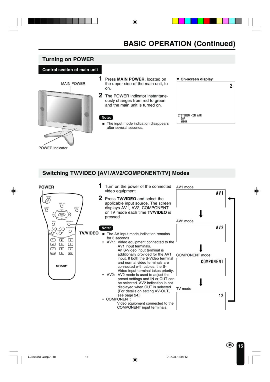
Control section of main unit
1 | Press MAIN POWER, located on |
MAIN POWER | the upper side of the main unit, to |
| on. |
2 | The POWER indicator instantane- |
| ously changes from red to green |
| and the main unit is turned on. |
Note: | |
■ | The input mode indication disappears |
| after several seconds. |
▼
2
![]() STEREO <ON A I R
STEREO <ON A I R
SAP
MONO
POWER indicator
Switching TV/VIDEO [AV1/AV2/COMPONENT/TV] Modes
POWER |
|
| 1 Turn on the power of the connected |
|
|
| video equipment. |
POWER |
|
| 2 Press TV/VIDEO and select the |
|
|
| |
| DISPLAY |
| applicable input source. The screen |
SLEEP |
| BRIGHT | displays AV1, AV2, COMPONENT |
| MENU |
| or TV mode each time TV/VIDEO is |
|
| pressed. | |
|
|
| |
MUTE |
| TV/VIDEO |
|
|
| FLASHBACK | Note: |
VOL | CH |
|
|
AV1 mode
A V 1
AV2 mode
A V 2
1 2 3
4 5 6
7 8 9
MTS 0 100
TV/VIDEO ■ The AV input mode indication remains for 3 seconds.
•AV1: Video equipment connected to the AV1 input terminals.
An
•AV2: AV2 mode is used to adjust the preset settings and IN or OUT can be selected. AV2 indication is not displayed when OUT is selected. (For details on setting
•COMPONENT:
Video equipment connected to the
COMPONENT input terminals.
COMPONENT mode
COMPON E N T
TV mode
1 2
15
15 | 01.7.23, 1:29 PM |