CIRCUIT MODIFICATION
To modify the microphone circuit for normally shorted operation, proceed as follows:
1. | Remove the three No. 6 Phillips screws from the back of the |
| microphone case. |
2. | Separate the front and back sections of the case, and remove |
| the |
3. | Unsolder or clip the GREEN cable lead from the |
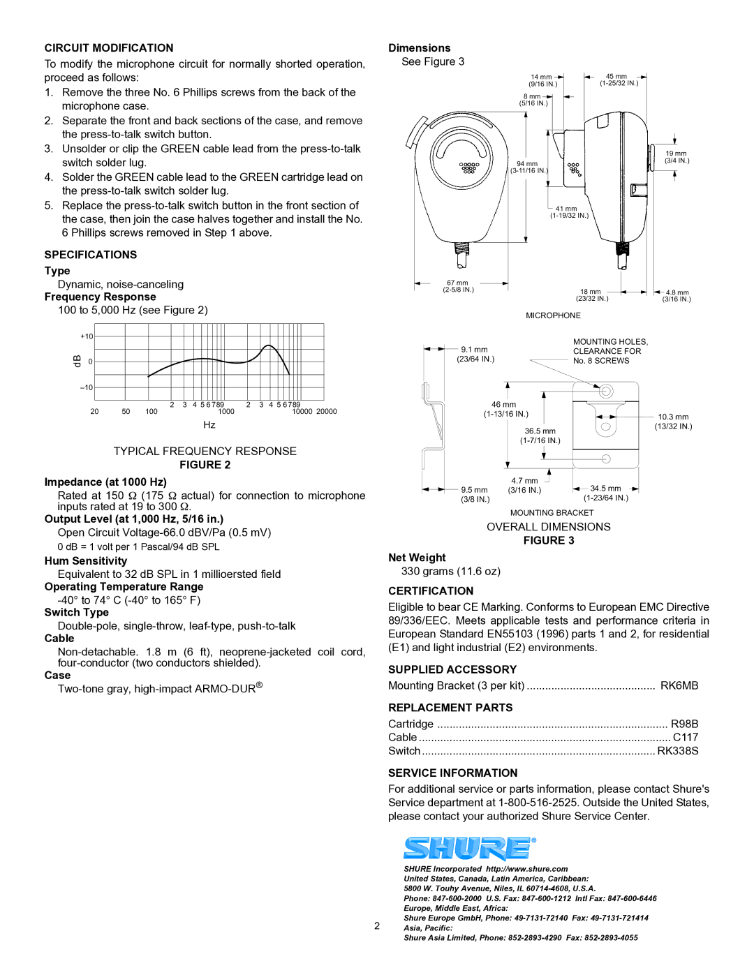
Dimensions
See Figure 3
14 mm | 45 mm |
(9/16 IN.) |
8 mm ![]() (5/16 IN.)
(5/16 IN.)
| switch solder lug. |
4. | Solder the GREEN cable lead to the GREEN cartridge lead on |
| the |
5. | Replace the |
94 mm
19 mm (3/4 IN.)
the case, then join the case halves together and install the No. |
6 Phillips screws removed in Step 1 above. |
SPECIFICATIONS
Type
Dynamic,
Frequency Response
100 to 5,000 Hz (see Figure 2)
41 mm
67 mm |
|
|
18 mm | 4.8 mm | |
| (23/32 IN.) | (3/16 IN.) |
MICROPHONE
+10
dB 0
20 | 50 | 2 | 3 | 4 5 6 789 | 2 | 3 | 4 5 6 789 |
100 |
| 1000 |
|
| 10000 20000 |
Hz
TYPICAL FREQUENCY RESPONSE
FIGURE 2
9.1mm
(23/64 IN.)
46 mm
36.5 mm
MOUNTING HOLES,
CLEARANCE FOR
No. 8 SCREWS
10.3 mm (13/32 IN.)
Impedance (at 1000 Hz)
Rated at 150 Ω (175 Ω actual) for connection to microphone inputs rated at 19 to 300 Ω.
Output Level (at 1,000 Hz, 5/16 in.)
Open Circuit
0 dB = 1 volt per 1 Pascal/94 dB SPL
Hum Sensitivity
Equivalent to 32 dB SPL in 1 millioersted field
Operating Temperature Range
Switch Type
Cable
Case
9.5 mm | 4.7 mm | 34.5 mm |
(3/16 IN.) | ||
(3/8 IN.) |
|
MOUNTING BRACKET
OVERALL DIMENSIONS
FIGURE 3
Net Weight
330 grams (11.6 oz)
CERTIFICATION
Eligible to bear CE Marking. Conforms to European EMC Directive 89/336/EEC. Meets applicable tests and performance criteria in European Standard EN55103 (1996) parts 1 and 2, for residential (E1) and light industrial (E2) environments.
SUPPLIED ACCESSORY |
|
Mounting Bracket (3 per kit) | RK6MB |
REPLACEMENT PARTS |
|
Cartridge | R98B |
Cable | C117 |
Switch | RK338S |
SERVICE INFORMATION
For additional service or parts information, please contact Shure's Service department at
| SHURE Incorporated http://www.shure.com |
| United States, Canada, Latin America, Caribbean: |
| 5800 W. Touhy Avenue, Niles, IL |
| Phone: |
| Europe, Middle East, Africa: |
2 | Shure Europe GmbH, Phone: |
Asia, Pacific: |
Shure Asia Limited, Phone:
