GENERAL
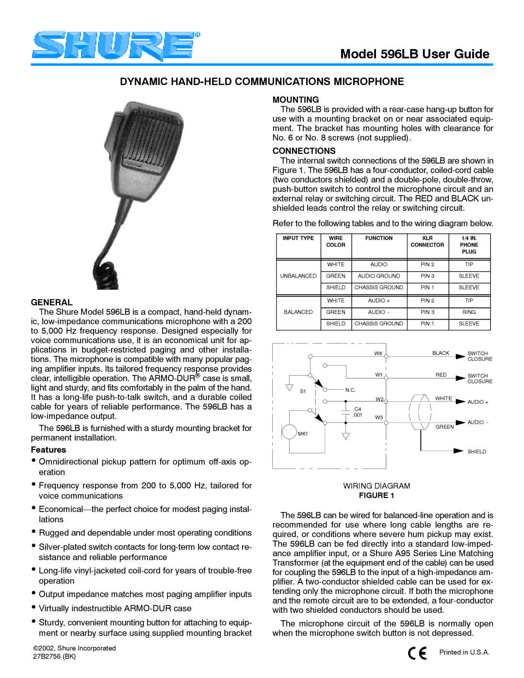
The Shure Model 596LB is a compact, hand-held dynam- ic, low-impedance communications microphone with a 200 to 5,000 Hz frequency response. Designed especially for voice communications use, it is an economical unit for ap- plications in budget-restricted paging and other installa- tions. The microphone is compatible with many popular pag- ing amplifier inputs. Its tailored frequency response provides clear, intelligible operation. The ARMO-DURcase is small, light and sturdy, and fits comfortably in the palm of the hand. It has a long-life push-to-talk switch, and a durable coiled cable for years of reliable performance. The 596LB has a low-impedance output.
The 596LB is furnished with a sturdy mounting bracket for permanent installation.
Features
•Omnidirectional pickup pattern for optimum off-axis op- eration
•Frequency response from 200 to 5,000 Hz, tailored for voice communications
•Economical—the perfect choice for modest paging instal- lations
•Rugged and dependable under most operating conditions
•Silver-plated switch contacts for long-term low contact re- sistance and reliable performance
•Long-life vinyl-jacketed coil-cord for years of trouble-free operation
•Output impedance matches most paging amplifier inputs
•Virtually indestructible ARMO-DUR case
•Sturdy, convenient mounting button for attaching to equip- ment or nearby surface using supplied mounting bracket
2002, Shure Incorporated 27B2756 (BK)
MOUNTING
The 596LB is provided with a rear-case hang-up button for use with a mounting bracket on or near associated equip- ment. The bracket has mounting holes with clearance for No. 6 or No. 8 screws (not supplied).
CONNECTIONS
The internal switch connections of the 596LB are shown in Figure 1. The 596LB has a four-conductor, coiled-cord cable (two conductors shielded) and a double-pole, double-throw, push-button switch to control the microphone circuit and an external relay or switching circuit. The RED and BLACK un- shielded leads control the relay or switching circuit.
Refer to the following tables and to the wiring diagram below.
INPUT TYPE | WIRE | FUNCTION | XLR | 1/4 IN. |
| COLOR | | CONNECTOR | PHONE |
| | | | PLUG |
| | | | |
| | | | |
| WHITE | AUDIO | PIN 2 | TIP |
| | | | |
UNBALANCED | GREEN | AUDIO GROUND | PIN 3 | SLEEVE |
| | | | |
| SHIELD | CHASSIS GROUND | PIN 1 | SLEEVE |
| | | | |
| | | | |
| WHITE | AUDIO + | PIN 2 | TIP |
| | | | |
BALANCED | GREEN | AUDIO – | PIN 3 | RING |
| | | | |
| SHIELD | CHASSIS GROUND | PIN 1 | SLEEVE |
| | | | |
| | W6 | BLACK | SWITCH |
| | | | CLOSURE |
| | W1 | RED | SWITCH |
| | | | CLOSURE |
S1 | N.C. | | | |
| | W2 | WHITE | AUDIO + |
| | | |
| C4 | | | |
| .001 | W3 | | |
| | | AUDIO – |
| | | GREEN |
| | | |
MK1 | | | | |
| | | | SHIELD |
WIRING DIAGRAM
FIGURE 1
The 596LB can be wired for balanced-line operation and is recommended for use where long cable lengths are re- quired, or conditions where severe hum pickup may exist. The 596LB can be fed directly into a standard low-imped- ance amplifier input, or a Shure A95 Series Line Matching Transformer (at the equipment end of the cable) can be used for coupling the 596LB to the input of a high-impedance am- plifier. A two-conductor shielded cable can be used for ex- tending only the microphone circuit. If both the microphone and the remote circuit are to be extended, a four-conductor with two shielded conductors should be used.
The microphone circuit of the 596LB is normally open when the microphone switch button is not depressed.
Printed in U.S.A.