Model A412B Microphone Base User Guide
GENERAL
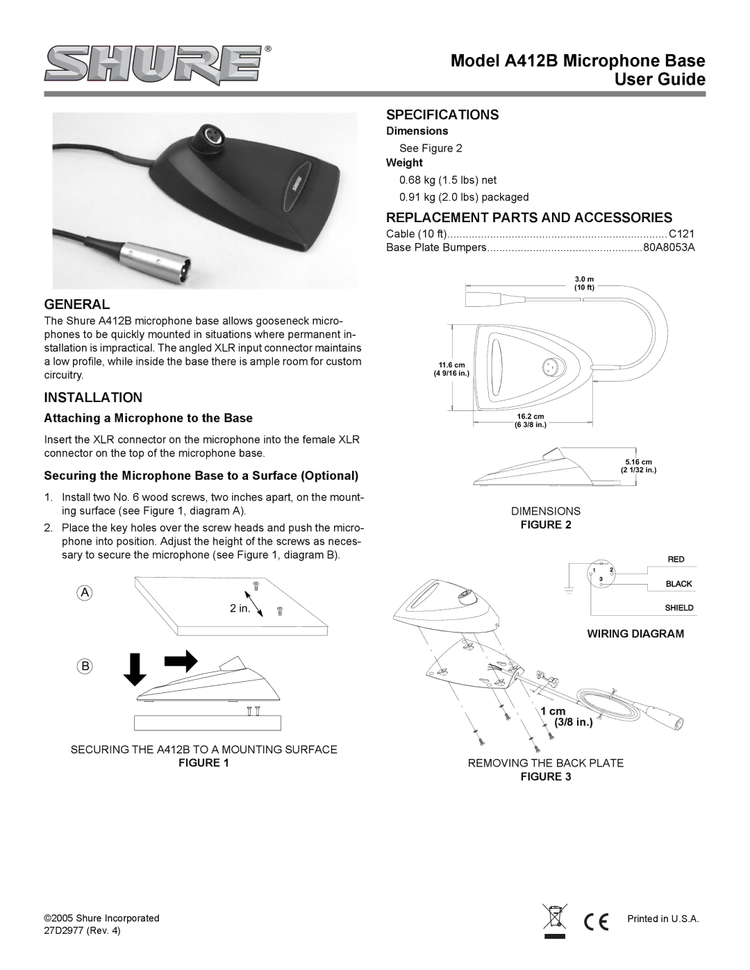
The Shure A412B microphone base allows gooseneck micro- phones to be quickly mounted in situations where permanent in- stallation is impractical. The angled XLR input connector maintains a low profile, while inside the base there is ample room for custom circuitry.
INSTALLATION
Attaching a Microphone to the Base
Insert the XLR connector on the microphone into the female XLR connector on the top of the microphone base.
Securing the Microphone Base to a Surface (Optional)
1.Install two No. 6 wood screws, two inches apart, on the mount- ing surface (see Figure 1, diagram A).
2.Place the key holes over the screw heads and push the micro- phone into position. Adjust the height of the screws as neces- sary to secure the microphone (see Figure 1, diagram B).
SPECIFICATIONS
Dimensions
See Figure 2
Weight
0.68 kg (1.5 lbs) net
0.91 kg (2.0 lbs) packaged
REPLACEMENT PARTS AND ACCESSORIES
Cable (10 ft) | C121 |
Base Plate Bumpers | 80A8053A |
| 3.0 m |
| (10 ft) |
11.6cm
(4 9/16 in.)
16.2cm
(6 3/8 in.)
5.16 cm
(2 1/32 in.)
DIMENSIONS
FIGURE 2
A
2 in.
WIRING DIAGRAM
B
| 1 cm |
| (3/8 in.) |
SECURING THE A412B TO A MOUNTING SURFACE |
|
FIGURE 1 | REMOVING THE BACK PLATE |
| FIGURE 3 |
©2005 Shure Incorporated |
| Printed in U.S.A. |
27D2977 (Rev. 4) |
|
|
|
|
|
