M367 specifications
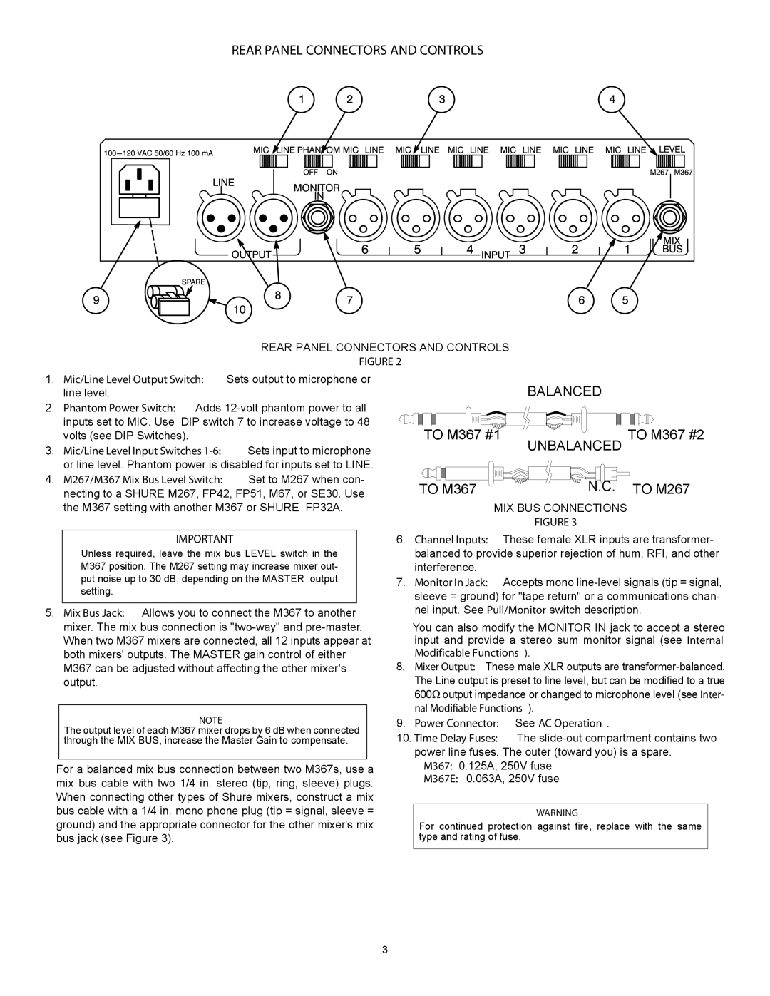
The Shure M367 is a premium audio mixing console designed for professional applications, renowned for its robust build quality and advanced functionalities. Specifically designed for use in live sound reinforcement and broadcasts, the M367 is a reliable choice for audio engineers and sound technicians.One of the standout features of the Shure M367 is its versatile channel configuration. With a total of six mono input channels, it allows for a variety of sources, including microphones and instruments. Each channel is equipped with high-quality preamplifiers, providing low noise and a wide dynamic range. This ensures that audio signals are captured with clarity and precision, essential for any professional setting.
The M367 features a flexible EQ section for each channel, utilizing a three-band equalizer with adjustable parameters. This allows users to tailor the tonal balance according to their specific needs, enhancing the overall audio experience. Additionally, the built-in low-cut filter helps eliminate unwanted low-frequency noise, making it easier to achieve a clean sound across various applications.
Another important aspect of the Shure M367 is its advanced routing capabilities. With multiple auxiliary sends, users can create independent mixes for stage monitors, effects processing, or recordings. The output section also offers balanced XLR outputs, ensuring that signals are transmitted cleanly with minimal interference.
Technologically, the M367 incorporates high-performance components designed to withstand the rigors of live sound environments. Its rugged chassis is built to endure extensive use, while intuitive controls make it user-friendly, even under pressure. This combination of durability and ease of use makes it a favorite among professionals.
Moreover, the M367 is equipped with comprehensive metering options, allowing for accurate monitoring of audio levels. This is critical in live sound situations, where ensuring clarity and balance is paramount. The console's design also includes a dedicated headphone output for monitoring, enabling sound engineers to listen closely to the mix.
In conclusion, the Shure M367 is a highly capable audio mixing console that combines professional-grade sound quality, extensive features, and rugged construction. Whether used for live performances, studio recordings, or broadcast applications, the M367 stands out as a reliable tool for achieving high-quality sound. With its robust technology and user-friendly design, it continues to be a preferred choice among audio professionals around the world.

