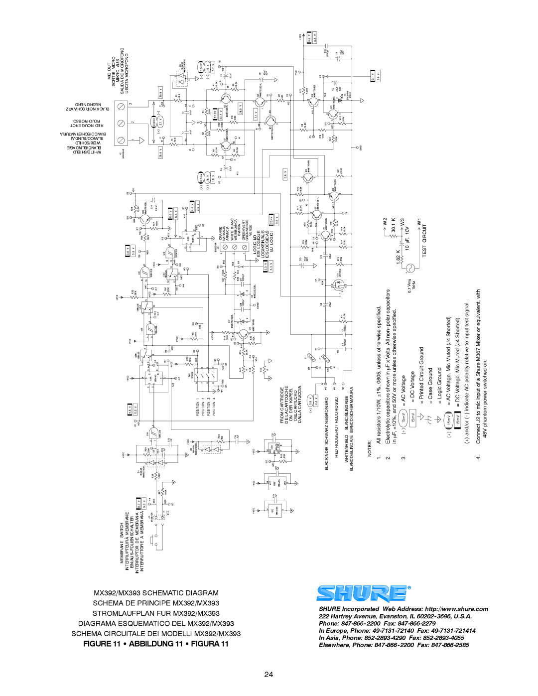
MX300 Series specifications
The Shure MX300 Series represents a significant advancement in professional audio technology, designed specifically for the nuances of theatrical performances, live events, and studio recording. These high-quality microphones are engineered to deliver exceptional sound clarity and reliability, making them an essential tool for audio professionals.One of the standout features of the MX300 Series is its versatile capsule design. The microphones utilize a proprietary cardioid pattern that effectively isolates the desired sound source while minimizing ambient noise from the surrounding environment. This directional sensitivity makes them ideal for stage use, where managing feedback and unwanted sound is crucial.
The MX300 Series incorporates advanced audio technologies, including integrated pop filters and shock mounts. These features help to reduce plosive sounds and vibrations that can detract from vocal performances. The result is a cleaner, more focused sound with less interference, allowing performers to project their voices confidently.
Durability is another hallmark of the MX300 Series. The microphones are constructed with a robust metal chassis designed to withstand the rigors of touring and frequent use. The rugged design ensures that the MX300 can handle the demands of both outdoor and indoor environments without compromising audio quality.
In addition to its physical durability, the MX300 Series boasts impressive frequency response characteristics. The microphones are engineered to capture a wide range of frequencies, from the rich lows of a deep bass voice to the sparkling highs of a soprano. This broad frequency range allows for a natural and accurate representation of the performer's voice, enhancing the overall listening experience.
The MX300 Series also features an intuitive user interface with convenient controls, making it easy for audio engineers to adjust settings on the fly. This level of user-friendly design ensures that both seasoned professionals and newcomers to the audio field can operate the microphones without extensive training.
In summary, the Shure MX300 Series is a remarkable line of microphones that combines innovative technology, durability, and superior sound quality. Whether for live performances, studio recordings, or broadcast applications, the MX300 Series delivers exceptional audio performance that meets the high standards of audio professionals around the world. With its thoughtful design and robust construction, it stands as a reliable choice for anyone seeking to elevate their sound production capabilities.

