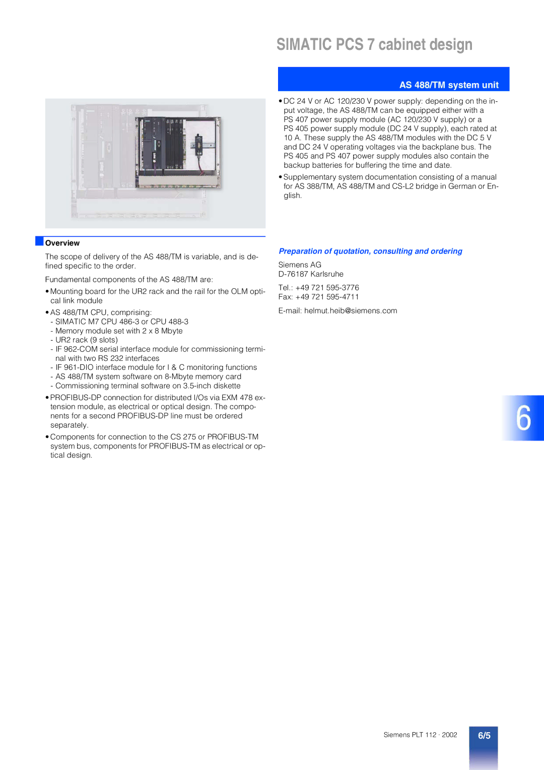
PCS 7 specifications
Siemens PCS 7 is a powerful and comprehensive process control system designed for various industrial automation applications. It is part of the Siemens Totally Integrated Automation (TIA) portfolio, providing seamless integration with various Siemens products and services. The system is known for its flexibility, scalability, and reliability, making it suitable for industries such as energy, water treatment, chemicals, pharmaceuticals, and manufacturing.One of the main features of Siemens PCS 7 is its modular architecture, which allows users to customize and scale their control solutions according to their specific needs. The system supports a diverse range of hardware and software components, from powerful servers and workstations to field devices and controllers. This modularity ensures that the system can adapt to different operational requirements while remaining cost-effective.
Another key feature is the advanced visualization capabilities offered by PCS 7. Users can create intuitive graphical interfaces that improve process monitoring and control. The system's Process Control and Monitoring (PCM) application enables real-time visualization of processes, enhancing decision-making and responsiveness.
Siemens PCS 7 is built on open and industry-standard communication protocols, such as Profibus and Profinet. This ensures interoperability with a wide array of third-party devices and systems, allowing seamless integration into existing infrastructures. The system supports a variety of communication interfaces, enhancing data exchange and connectivity within the control architecture.
The PCS 7 system also incorporates sophisticated process automation technologies, including batch control, continuous process control, and advanced process control algorithms. These capabilities not only facilitate efficient operation but also optimize production processes through improved resource management and reduced waste.
Security is a critical aspect of Siemens PCS 7, addressing the growing concerns of cybersecurity in industrial environments. The system incorporates robust security measures, including user authentication, data encryption, and regular software updates, ensuring that industrial operations remain protected against potential threats.
In summary, Siemens PCS 7 exemplifies modern industrial automation technology with its modularity, advanced visualization, open communication, sophisticated process control capabilities, and strong security features. Whether adapting to new technologies or optimizing existing operations, PCS 7 stands as a versatile and resilient platform for today's diverse industrial automation challenges.

