Temporary timer for extended presence or absence

The Comfort and Economy modes can be temporarily extended by 0.5 to 9.5 hours using the temporary timer.

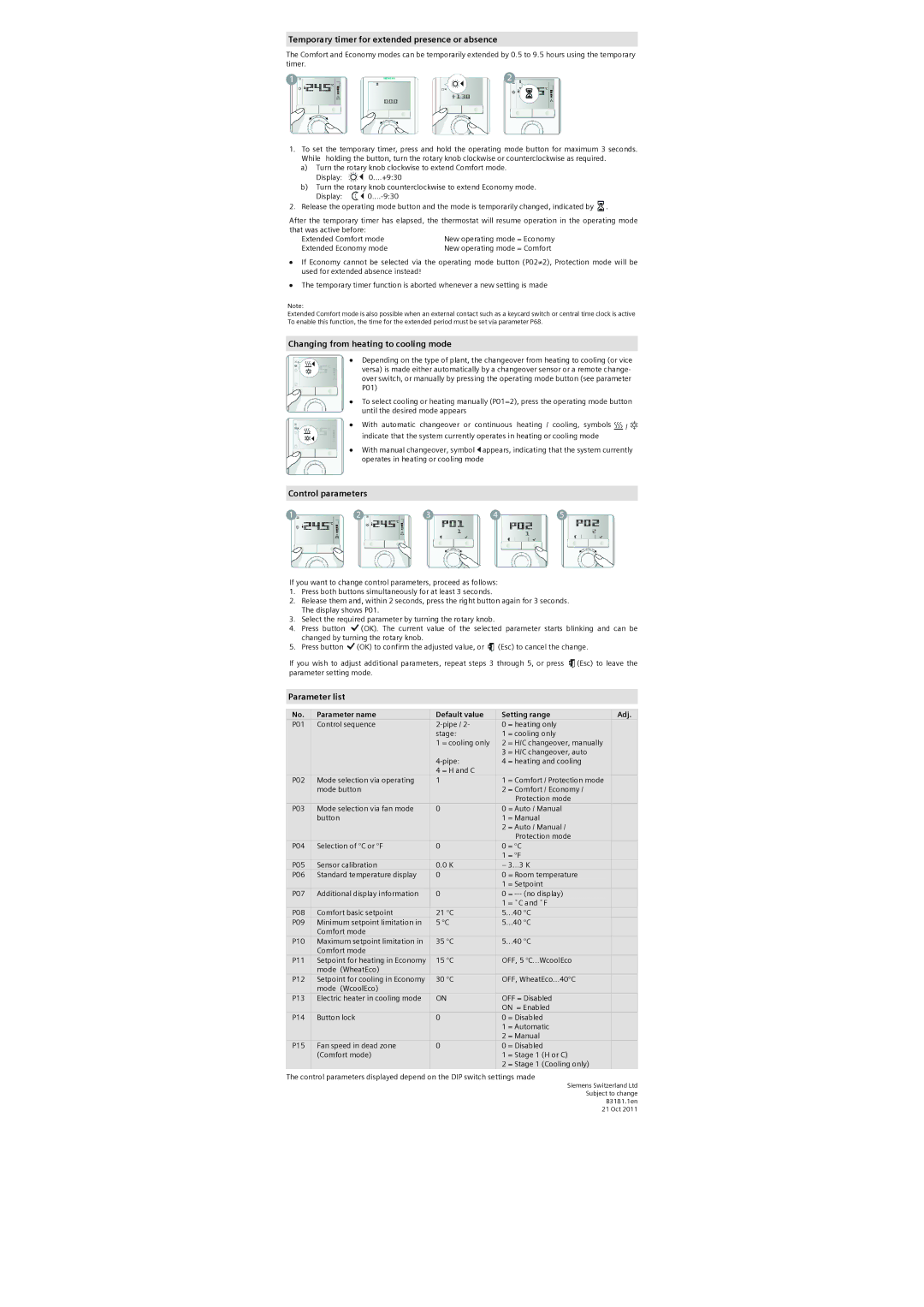
1.To set the temporary timer, press and hold the operating mode button for maximum 3 seconds. While holding the button, turn the rotary knob clockwise or counterclockwise as required.

a)Turn the rotary knob clockwise to extend Comfort mode.

Display: 0....+9:30

b)Turn the rotary knob counterclockwise to extend Economy mode.

Display: 0....-9:30

2. Release the operating mode button and the mode is temporarily changed, indicated by .

After the temporary timer has elapsed, the thermostat will resume operation in the operating mode

that was active before:


Extended Comfort mode

New operating mode = Economy

Extended Economy mode

New operating mode = Comfort

If Economy cannot be selected via the operating mode button (P02≠2), Protection mode will be used for extended absence instead!

The temporary timer function is aborted whenever a new setting is made

Note:

Extended Comfort mode is also possible when an external contact such as a keycard switch or central time clock is active To enable this function, the time for the extended period must be set via parameter P68.

Changing from heating to cooling mode

Depending on the type of plant, the changeover from heating to cooling (or vice versa) is made either automatically by a changeover sensor or a remote change- over switch, or manually by pressing the operating mode button (see parameter P01)

To select cooling or heating manually (P01=2), press the operating mode button until the desired mode appears

With automatic changeover or continuous heating / cooling, symbols / indicate that the system currently operates in heating or cooling mode

With manual changeover, symbol appears, indicating that the system currently operates in heating or cooling mode

Control parameters

If you want to change control parameters, proceed as follows:

1.Press both buttons simultaneously for at least 3 seconds.

2.Release them and, within 2 seconds, press the right button again for 3 seconds. The display shows P01.

3.Select the required parameter by turning the rotary knob.

4.Press button (OK). The current value of the selected parameter starts blinking and can be changed by turning the rotary knob.

5.Press button (OK) to confirm the adjusted value, or (Esc) to cancel the change.

If you wish to adjust additional parameters, repeat steps 3 through 5, or press (Esc) to leave the parameter setting mode.

Parameter list

No.

Parameter name

Default value

Setting range

Adj.

P01

Control sequence

2-pipe / 2-

0

= heating only


stage:

1

= cooling only


1 = cooling only

2

= H/C changeover, manually


3

= H/C changeover, auto


4-pipe:

4

= heating and cooling


4 = H and C


P02

Mode selection via operating

1

1

= Comfort / Protection mode


mode button


2

= Comfort / Economy /


Protection mode


P03

Mode selection via fan mode

0

0

= Auto / Manual


button


1

= Manual


2

= Auto / Manual /


Protection mode


P04

Selection of °C or °F

0

0

= °C


1

= °F


P05

Sensor calibration

0.0 K

– 3…3 K


P06

Standard temperature display

0

0

= Room temperature


1

= Setpoint


P07

Additional display information

0

0

= --- (no display)


1

= ˚C and ˚F


P08

Comfort basic setpoint

21 °C

5…40 °C


P09

Minimum setpoint limitation in

5 °C

5…40 °C


Comfort mode


P10

Maximum setpoint limitation in

35 °C

5…40 °C


Comfort mode


P11

Setpoint for heating in Economy

15 °C

OFF, 5 °C…WcoolEco


mode (WheatEco)


P12

Setpoint for cooling in Economy

30 °C

OFF, WheatEco…40°C


mode (WcoolEco)


P13

Electric heater in cooling mode

ON

OFF = Disabled


ON = Enabled


P14

Button lock

0

0

= Disabled


1

= Automatic


2

= Manual


P15

Fan speed in dead zone

0

0

= Disabled


(Comfort mode)


1

= Stage 1 (H or C)


2

= Stage 1 (Cooling only)


The control parameters displayed depend on the DIP switch settings made

Siemens Switzerland Ltd

Subject to change

B3181.1en

21 Oct 2011

Page 2
Image 2
Siemens 110 Temporary timer for extended presence or absence, Changing from heating to cooling mode, Control parameters

160, 110, 140, RDG100 specifications

Siemens has long been a leader in the manufacturing of railway signaling and control systems, and their product lineup includes the Siemens 110, RDG100, 140, and 160, which feature advanced technologies designed to enhance the safety and efficiency of rail operations.

The Siemens 110 series is known for its versatility and robust construction, making it an ideal solution for various rail environments. It integrates advanced electronic signaling technologies, improving operational safety and reliability. Its modular design allows for easy upgrades and maintenance, ensuring that the systems can adapt to evolving rail network demands. Additionally, the 110 series is equipped with state-of-the-art fault detection, enhancing overall system reliability.

The RDG100, an innovative signaling relay, takes a step further with its digital technology. Its compact design allows for efficient space utilization while providing powerful signal processing capabilities. The RDG100 utilizes advanced microprocessor technology that ensures rapid response times and precise control over signaling operations. Its self-diagnosis features allow for real-time monitoring, significantly reducing downtime and enhancing operational reliability.

The Siemens 140 series focuses on providing high-performance signaling solutions, particularly in larger rail networks. It features a high level of integration and interoperability with existing systems. The 140 series utilizes cutting-edge communication protocols, ensuring seamless data exchange between different components of the signaling system. This feature is crucial for maintaining coordination among various trains and enhancing overall network efficiency.

Similarly, the Siemens 160 series is a next-generation signaling technology designed for high-speed rail applications. It incorporates advanced automation features that streamline train operations and reduce the likelihood of human error. The 160 series employs sophisticated algorithms for traffic management, enabling it to optimize train schedules and improve overall throughput. Moreover, its resilience to environmental factors ensures that it functions optimally even in harsh conditions.

In summary, Siemens’ 110, RDG100, 140, and 160 series represent a comprehensive range of signaling and control solutions tailored for modern railway operations. With their focus on modularity, digital technology, integration, and automation, these systems are at the forefront of the railway industry, driving safety, efficiency, and reliability in rail transportation. As rail networks continue to expand and modernize, these Siemens products will be critical in shaping the future of train signaling and control strategies.