Connections
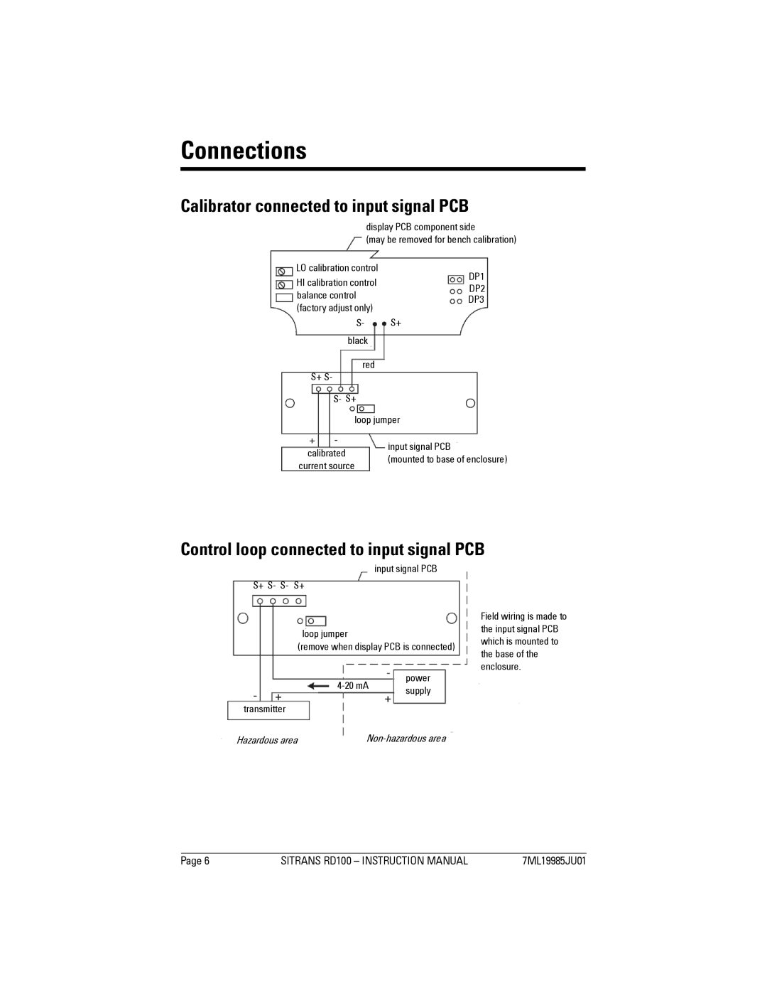
Calibrator connected to input signal PCB
display PCB component side
(may be removed for bench calibration)
LO calibration control |
|
|
|
|
|
| DP1 |
|
|
|
|
|
|
| |
HI calibration control |
|
|
|
|
| ||
|
|
|
|
|
| DP2 | |
|
|
|
|
|
| ||
|
|
|
|
|
|
| |
balance control |
|
|
|
|
|
|
|
|
|
|
|
|
| DP3 | |
(factory adjust only) |
|
|
|
|
|
| |
|
|
|
|
|
|
| |
S- |
|
|
|
| |||
|
| S+ | |||||
black |
|
|
|
|
|
|
|
red
S+ S-
S- S+
|
|
|
|
|
|
| |
|
| loop jumper | |||||
|
|
|
|
|
|
| |
|
|
|
|
| input signal PCB | ||
| calibrated |
|
|
|
| ||
|
|
|
| (mounted to base of enclosure) |
| ||
| current source |
|
|
| |||
|
|
|
|
|
| ||
|
|
|
|
|
|
|
|
Control loop connected to input signal PCB
input signal PCB
S+ S- S- S+
loop jumper
(remove when display PCB is connected)
| power |
supply | |
|
transmitter
Field wiring is made to the input signal PCB which is mounted to the base of the enclosure.
Hazardous area |
|
Page 6 | SITRANS RD100 – INSTRUCTION MANUAL | 7ML19985JU01 |