


 Cut Along


 Line
Line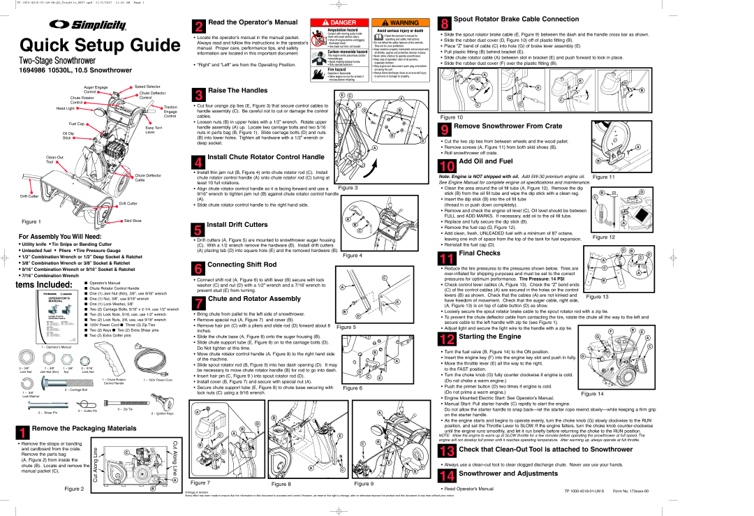
10530L, 10.5, 1694986 specifications
Simplicity 10530L is an innovative and versatile riding lawn mower designed to simplify yard maintenance for homeowners and professionals alike. Equipped with a robust 10.5-horsepower engine, this mower offers impressive power and performance to tackle different terrains and dense grass with ease.One of the standout features of the Simplicity 10530L is its unique All-Wheel Drive system. This technology provides superior traction across various surfaces, ensuring a confident grip even on steep inclines or uneven ground. The system automatically adjusts power to the wheels, allowing for smooth maneuverability and control, making it ideal for properties with diverse landscapes.
The mower is also equipped with a 30-inch cutting deck, which is perfect for navigating tight spaces and narrow pathways that larger mowers might struggle with. This compact size does not compromise its cutting capabilities. The deck utilizes a three-blade system, delivering a clean and precise cut every time, regardless of the grass type or thickness. Additionally, it features an easy-to-use height adjustment mechanism, allowing users to customize their cutting height according to their lawn's specific needs.
Comfort and convenience are at the forefront of the Simplicity 10530L design. The operator's seat is ergonomically designed for enhanced comfort during prolonged use. With a smooth and responsive steering mechanism, users can enjoy effortless maneuvering around obstacles, trees, and flower beds. Furthermore, the mower comes with a spacious storage compartment under the seat, providing a practical solution for keeping tools and personal items within reach.
Simplicity also emphasizes durability in the construction of the 10530L. The mower is built with high-quality materials that resist wear and tear, ensuring longevity and reliability. The easy-access maintenance points are designed to simplify regular upkeep, making it easy for users to perform routine checks and services.
In conclusion, the Simplicity 10530L, with its powerful performance, advanced All-Wheel Drive technology, compact cutting deck, and user-friendly design, stands out as a top choice for anyone seeking an efficient and reliable riding lawn mower. Whether your lawn is large or small, this model is equipped to handle it all, making yard work a simpler and more enjoyable experience.