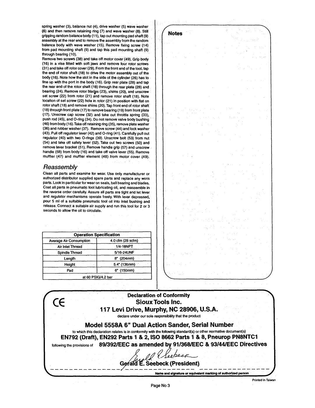
spring washer (3). balance nut (4). drive washer (5) wave washer
(6) and then remove retaining ring (7) and wave washer (8). Still
grippingrandombalancebody (1l),tap out mountingpadshaft (9)Notes assembly at the rear end to remove the assembly fromthe random
balance body with wave washer (15). Remove fixing screw (14) from pad mounting shaft (9) and tap this pad mounting shaft (9) through bearing (10).
Removetwo screws (38) and take off motor cover (49). Grip body
(16)in a vise fitted with soft jaws and remove four rotor screws
(31)andtake off rotorcover (29). Fromthe front end of the tool, tap the end of rotor shaft (18) to drive the motor assembly out of the body (16). Note how the slot in the side of the cylindei(26) has to line up with the port in the body (16). Grip rear plate (28) and tap the rear end of the rotor shaft (18) through the rear plate (28) and bearing(24). Remove rotor blades (23), shims (20). and unscrew set screw (22) from rotor (21) and remove rotor shaft (18). Note locationof set screw (22) hole in rotor (21) in positionwith flat on rotorshaft (18) and removeshims (20). Tap front endof rotor shaft
(18)throughfront plate(17) to removebearing(19) fromfront plate
(17).Unscrew cap screw (32) and take out throttle spring (33). push rod (45). and
(46)frombody(16).Take off retainingring(35), removeplate washer
(36)and rubberwasher (37). Removescrew (44) and lock washer
(43).Pull off regulator lever (42) and
(54)and take off safety lever (52). Take out two screws (50) and remove lever bracket (51). Remove handle grip (57) and unscrew handle (58) from body (16) and take off valve lever (55). Remove muffler (47) and muffler element (48) trom motor cover (49).
Reassembly
Clean all parts and examine for wear. Use only manufacturer or authorized distributor supplied spare parts and replace any worn parts. Lookin particularfor wear on seals, ball bearingandblades. Coat all parts in pneumatictool lubricatingoil, and reassemble in the reverse order carefully. Assure all parts are tight and let lever and regulator mechanisms operate freely. With (ever depressed, pour 5 mi of a suitable pneumatic tool oil into inlet bushing and release.Connect a suitable air supply and run this tool for 2 or 3 seconds to allow the oil to circulate.
Operation Specification
Average Air Consumption | 4.0 d m (28 scfm) |
Air InletThread | |
Spindle Thread | |
t | 8" (204mm) |
Length | |
Height | 5.4" (136mm) |
Pad | 6" (150mm) |
I
at 60 PSIGl4.2 bar | 1 |
I .
r | cc | Declaration of Conformity |
| SiouxTools Inc. | |
|
| |
|
| 117 Levi Drive, Murphy, NC 28906, U.S.A. |
|
| declare under our sole responsibilitythat the product |
|
| Model 5558A 6" Dual Action Sander, Serial Number |
|
| to which this declaration relates is in conformity with the following standard(s) or other normativedocument(s) |
EN792 (Draft), EN292 Parts 1 & 2, IS0 8662 Parts 1 & 8, Pneurop PN8NTC1
following the provisions of 89139ZEEC&as amended by 91/368/EEC & 93144fEEC Directives
f A L
G a .Seebeck (President)
Page No 3
