E.Butt connect the battery cable wires to the red and red/black wires on the power cable. Route cable to the battery and connect to the positive (+) terminal, or an auxiliary terminal block as provided some vehicles.
F.WHITE WIRE (Ignition Sense) is routed to the fuse block or other ignition source. This wire must see +12 volts when the key is turned on or the
CAUTION: The battery cable connector and ignition sense lead are both fused for the
DAMAGE COULD RESULT.
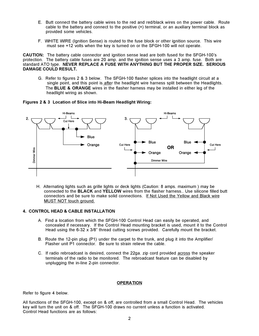
G.Refer to figures 2 & 3 below. The
The BLUE & ORANGE wires in the flasher harness may be installed in either leg of the headlight wiring as shown.
Figures 2 & 3 Location of Slice into Hi-Beam Headlight Wiring:
H.Alternating lights such as grille lights or deck lights (Caution: 8 amps. maximum ) may be connected to the BLACK and YELLOW wires from the flasher harness.. Use silicone filled butt connectors and be sure to make solid connections. If Not Used the Yellow and Black wire MUST NOT touch ground.
4.CONTROL HEAD & CABLE INSTALLATION
A.Find a location from which the
B.Route the
C.If radio rebroadcast is desired, connect the 22ga. zip cord provided across the speaker terminals of the radio to be monitored. The rebroadcast feature can be disabled by unplugging the
OPERATION
Refer to figure 4 below.
All functions of the
Control Head functions are as follows:
2