Wiring and Cable Connections
A
PIONEER COMPATIBLE
SIRIUS SATELLITE RADIO TUNER
IP BUS
B | C | D |
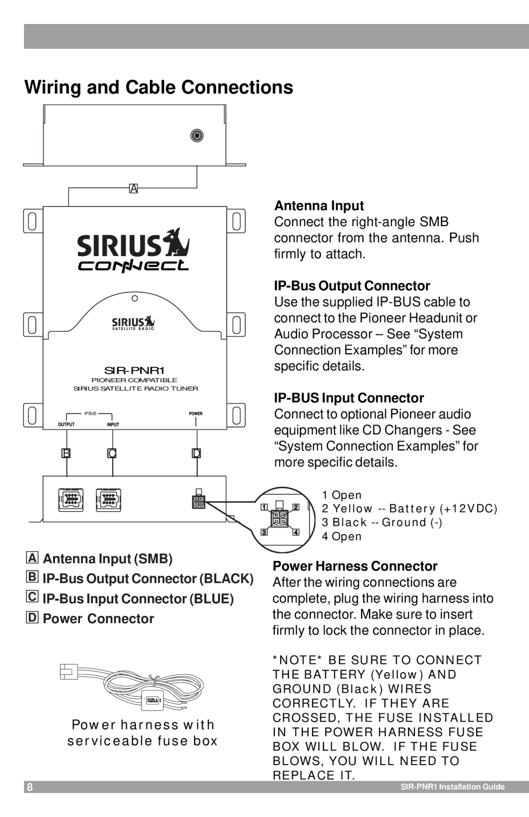
Antenna Input
Connect the
IP-Bus Output Connector
Use the supplied
|
| 1 Open |
1 | 2 | 2 Yellow |
|
| 3 Black |
3 | 4 | 4 Open |
|
AAntenna Input (SMB)
B
C
DPower Connector
IN | FUSE BOX | UTO |
| FILTER & |
|
Power harness with serviceable fuse box
Power Harness Connector After the wiring connections are complete, plug the wiring harness into the connector. Make sure to insert firmly to lock the connector in place.
*NOTE* BE SURE TO CONNECT THE BATTERY (Yellow) AND GROUND (Black) WIRES CORRECTLY. IF THEY ARE CROSSED, THE FUSE INSTALLED IN THE POWER HARNESS FUSE BOX WILL BLOW. IF THE FUSE BLOWS, YOU WILL NEED TO REPLACE IT.
8 |
|