BM 1619X01517
DRILL BIT STORAGE COMPARTMENT
AND QUICK REFERENCE GAUGE
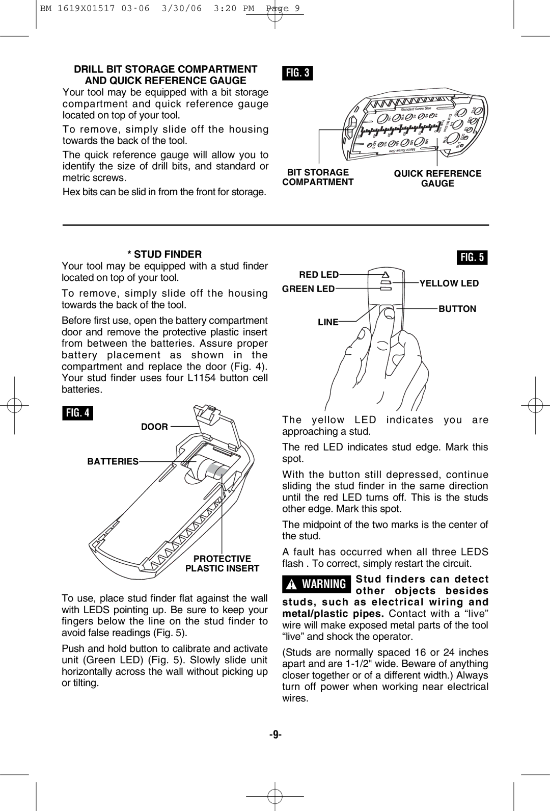
Your tool may be equipped with a bit storage compartment and quick reference gauge located on top of your tool.
To remove, simply slide off the housing towards the back of the tool.
The quick reference gauge will allow you to identify the size of drill bits, and standard or metric screws.
Hex bits can be slid in from the front for storage.
FIG. 3
BIT STORAGE | QUICK REFERENCE |
COMPARTMENT | GAUGE |
* STUD FINDER
Your tool may be equipped with a stud finder located on top of your tool.
FIG. 5
RED LED
To remove, simply slide off the housing towards the back of the tool.
GREEN LED
![]()
![]() YELLOW LED
YELLOW LED
BUTTON
Before first use, open the battery compartment door and remove the protective plastic insert from between the batteries. Assure proper battery placement as shown in the compartment and replace the door (Fig. 4). Your stud finder uses four L1154 button cell batteries.
FIG. 4
DOOR
BATTERIES
PROTECTIVE
PLASTIC INSERT
LINE
The yellow LED indicates you are approaching a stud.
The red LED indicates stud edge. Mark this spot.
With the button still depressed, continue sliding the stud finder in the same direction until the red LED turns off. This is the studs other edge. Mark this spot.
The midpoint of the two marks is the center of the stud.
A fault has occurred when all three LEDS flash . To correct, simply restart the circuit.
To use, place stud finder flat against the wall with LEDS pointing up. Be sure to keep your fingers below the line on the stud finder to avoid false readings (Fig. 5).
Push and hold button to calibrate and activate unit (Green LED) (Fig. 5). Slowly slide unit horizontally across the wall without picking up or tilting.
!WARNING Stud finders can detect other objects besides
studs, such as electrical wiring and metal/plastic pipes. Contact with a “live” wire will make exposed metal parts of the tool “live” and shock the operator.
(Studs are normally spaced 16 or 24 inches apart and are
