PLUMBING THE HUMIDIFIER:
5.0Select the nearest cold water pipe and install the saddle connector and needle valve, supplied with this unit. Use copper tubing only.
The needle valve is a self-piercing valve when installed on copper pipe. Follow the instructions supplied with the valve.
Mount the valve so that water will come from the top or side. This will reduce the chance of minerals clogging the valve.
5.1 Follow these compression plumbing tips:
Lightly clean the tubing ends with fine sandpaper before making connec- tions.
Make sure the tubing is fully inserted into the fitting before tightening the compression nut.
5.2IMPORTANT: After attaching the saddle valve, thoroughly flush the supply tubing to clear the line. Otherwise, debris could block the water flow at the solenoid valve.
5.3IMPORTANT: To assist you with cleaning, note the proper orientation of parts for assembly and disassembly (Figure 4, below).
Figure 4
5.4Slide the hex nut over the copper tubing end. Slide the brass ferrule over the tubing. Push the end of the tubing into the threaded fitting and slide the hex nut up to the fitting. Tighten the nut.
5.5Slide the bushing over the tubing; insert the bushing through the humidifier wall until it snaps into place.
5.6Open the needle valve at the cold water pipe. IMPORTANT: Check all fit- tings for leaks.
MOUNTING THE HUMIDISTAT:
6.0NOTE: See the installation instructions packaged with the enclosed humidi- stat (humidity controller).
6.1NOTE: When wiring the unit to a system that has a multi-speed blower mo- tor, or that uses a motor other than 120 VAC, include the Skuttle A50 Interface Relay in your installation.
Wiring Diagram / Figure 5
HUMIDIFIER CHECKOUT:
Check the humidifier operation by following these procedures:
7.0Turn on the water valve to the humidifier.
7.1Turn the humidistat to the “ON” position.
7.2Set the furnace thermostat high enough to allow the furnace to come on. When the furnace blower comes on, the humidifier should start spraying (provided there is enough heat reaching the humidifier thermostat).
7.3Check the humidifier operation by turning the humidistat off, making sure the humidifier stops spraying. NOTE: If the humidifier continues spraying, there may be an error in wiring. Review the wiring diagram, above.
7.4Set the furnace thermostat low enough to allow the furnace to shut off. The humidifier should stop spraying either before or as the furnace blower shuts off. NOTE: Again, if the humidifier continues spraying, there may be an error in writ- ing. Consult the wiring diagram.
7.5If the humidifier shuts off correctly, repeat steps 6.2 through 6.4 at least five times. Each time, check to see that no water impinges on ductwork or any part of the heating system. NOTE: If water impingement or fallout could occur, you must install a suitable drain pan, plumbed with an adequate runoff drain.
7.6Set the furnace thermostat to the desired setting.
7.7Finally, set the humidistat as recommended in Table 1, on the front of these instructions.
HUMIDIFIER PARTS:
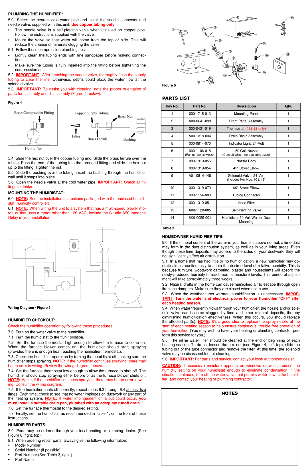
8.0Parts may be ordered through your local heating or plumbing dealer. (See Figure 6, right, top).
8.1When ordering repair parts, always give the following information: Model Number
Serial Number (if possible)
Part Number (See Table 3, right.) Part Name
Figure 6
PARTS LIST
Key No. | Part No. | Description | Qty. |
| | | |
1 | 000-1715-013 | Mounting Panel | 1 |
| | | |
2 | A00-0641-099 | Front Panel Assembly | 1 |
| | | |
3 | 000-0431-019 | Thermostat (592-22 only) | 1 |
| | | |
4 | A00-1319-034 | Drain Basin Assembly | 1 |
| | | |
5 | 000-0814-070 | Indicator Light, 24-Volt | 1 |
| | | |
6 | 000-1106-018 | .50 Gal. Nozzle | 1 |
| (Part no. varies w/size) | (Consult whlslr. for available sizes) | |
| | | |
7 | 000-1319-055 | Nozzle Body | 1 |
| | | |
8 | 000-1319-054 | 45° Street Elbow | 1 |
| | | |
9 | A01-0814-148 | Solenoid Valve, 24-Volt | 1 |
| | (includes Key Nos. 10 & 12) | |
| | | |
10 | 000-1319-070 | 90° Street Elbow | 1 |
| | | |
11 | 000-1154-000 | Tubing Connector | 1 |
| | | |
12 | 000-1319-051 | Inline Filter | 1 |
| | | |
13 | A00-1128-005 | Self-Piercing Valve | 1 |
| | | |
14 | SK0-0055-001 | Humidistat 24-Volt Wall or Duct | 1 |
| | Mounting | |
| | | |
Table 3 | | | |
HOMEOWNER HUMIDIFIER TIPS:
9.0If the mineral content of the water in your home is above normal, a lime dust may form in the duct distribution system, as well as in your living areas. Even though these lime deposits may adhere to the sides of your ductwork, they will not significantly affect air distribution.
9.1In a home that has had little or no humidification, a new humidifier may op- erate almost continuously to attain the desired level of relative humidity. This is because furniture, woodwork carpeting, plaster and houseplants will absorb the newly-produced humidity to reach normal moisture levels. This period of adjust- ment will take approximately three weeks.
9.2Natural drafts in the home can cause humidified air to escape through open fireplace dampers. Make sure they are closed when not in use.
9.3When the weather turns warmer, humidification is unnecessary. IMPOR-
TANT: Turn the water and electrical power to your humidifier ‘OFF” after each heating season.
9.4When water frequently flows through your humidifier, the nozzle and/or sole- noid valve can become clogged by lime and other mineral deposits, thereby diminishing humidification effectiveness. When this occurs, you should replace the affected part(s). NOTE: It’s a good idea to replace the spray nozzle at the start of each heating season to help ensure continuous, trouble-free operation of your humidifier. (You may wish to have your heating or plumbing contractor per- form this service for you.)
9.5The inline water filter should be cleaned at the end or beginning of each heating season. To do so, loosen the hex nut (see Figure 4, left, top), slide the tubing out of the tube connector and remove the filter. At this time, the solenoid valve may be disassembled for cleaning.
9.6IMPORTANT: For parts and service, contact your local authorized dealer.
CAUTION: If excessive moisture appears on windows or walls, reduce the humidity setting on your humidistat enough to eliminate condensation. If the situation continues, turn off the water valve that permits water flow to the humidi- fier, and contact your heating or plumbing contractor.
NOTES