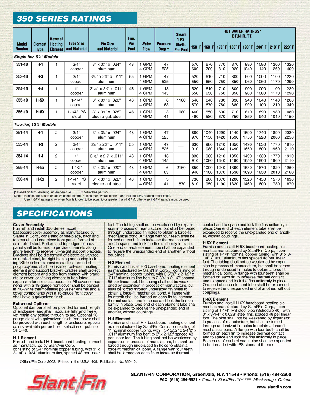
Slant/Fin 350 Series manual Series Ratings, Specifications, Single-tier,9 7⁄8” Models

Models: 350 Series

1 4
Download 4 pages 10.11 Kb
Page 4
Image 4
350 SERIES RATINGS

350 SERIES RATINGSSingle-tier, 9 7⁄8” ModelsTwo-tier, 13 7⁄8” ModelsSPECIFICATIONS


Steam


HOT WATER RATINGS*


Rows of


Fins


BTU/HR./FT.


1 PSI


Model

Element

Heating

Tube Size

Fin Size

Per

Water

Pressure

Btu/Hr.


150˚ F

160˚ F

170˚ F

180˚ F

190˚ F

200˚ F

210˚ F

220˚ F


Number

Type

Element

and Material

and Material

Foot

Flow

Drop †

Per Foot


Single-tier, 9 78” Models


351-10

H-1

1


3/4"

3" x 314" x .024"

48

1 GPM

47


570

670

770

870

980

1080

1200

1320


copper

aluminum


4 GPM

525


600

700

810

920

1040

1140

1260

1400


353-10

H-3

1


3/4"

3532" x 212" x .011"

55

1 GPM

47


520

610

710

800

900

1000

1100

1220


copper

aluminum


4 GPM

525


550

650

750

850

960

1060

1170

1290

354-10

H-4

1


1"

31532" x 212" x .011"

48

1 GPM

13


520

610

710

800

900

1000

1100

1220


copper

aluminum


4 GPM

145


550

650

750

850

960

1060

1170

1290

355-10

H-5X

1


1-1/4"

3" x 314" x .020"

48

1 GPM

6

1160


540

640

730

830

940

1040

1140

1260


copper

aluminum


4 GPM

63


570

670

780

880

990

1100

1210

1340


356-10

H-6X

1

1-1/4" IPS

3" x 314" x .028"

48

1 GPM

3

980


460

550

630

710

810

890

980

1080


steel

electro-gal. steel


4 GPM

41


490

580

670

750

850

940

1040

1150


Two-tier, 13 78” Models


351-14

H-1

2


3/4"

3" x 314" x .024"

48

1 GPM

47


880

1040

1290

1440

1590

1740

1890

2030


copper

aluminum


4 GPM

525


970

1150

1420

1590

1750

1920

2080

2250


353-14

H-3

2


3/4"

3532" x 212" x .011"

55

1 GPM

47


830

980

1210

1350

1490

1630

1770

1910


copper

aluminum


4 GPM

525


910

1080

1340

1490

1650

1800

1960

2110


354-14

H-4

2


1"

31532" x 212" x .011"

48

1 GPM

13


830

980

1210

1350

1490

1630

1770

1910


copper

aluminum


4 GPM

145


910

1080

1340

1490

1650

1800

1960

2110

355-14

H-5x

2


1-1/2"

3" x 314" x .020"

48

1 GPM

6

2160


850

1000

1240

1390

1530

1670

1820

1960


copper

aluminum


4 GPM

63


940

1100

1370

1530

1690

1850

2010

2160

356-14

H-6x

2

1-1/4" IPS

3" x 314" x .028"

48

1 GPM

3


730

860

1070

1200

1320

1450

1570

1690


steel

electro-gal. steel


4 GPM

41

1870


810

950

1190

1320

1460

1600

1730

1870


[* Based on 65°F entering air temperature

† Millinches per foot.


Note: Ratings are based on active finned length (3" less than overall length), and include 15% heating effect factor.


Use 4 GPM ratings only when flow is known to be equal to or greater than 4 GPM; otherwise 1 GPM ratings must be used.


SPECIFICATIONSManual backgroundManual backgroundManual backgroundManual backgroundManual background

Cover Assembly

Furnish and install 350 Series model_______

baseboard cover assembly as manufactured by Slant/Fin Corp., consisting of one-piece, back and top panel, and one-piece front panel, formed of cold rolled steel. Bottom and top edges of back panel shall be formed to provide channels along entire length, to receive full-height support brackets. Brackets shall be die-formed of electro galvanized cold rolled steel, for rigid bracing and spring lock- ing. Slide-action expansion cradles, formed of polypropylene, shall be inserted between heating element and support bracket. Cradles shall protect element bottom and sides from contact with brack- ets or cover, confining element to free lateral expansion for noiseless operation. All cover compo- nents with a 19-gauge front cover shall be painted in Nu-White thermosetting polyester enamel and all cover components with a 16-gauge front cover shall have a galvanized finish.

Extra-cost Options

Optional damper shall be provided for each length of enclosure, and shall modulate fully and freely, yet retain any setting through its arc. Optional 16- gauge steel with galvanized finish front cover shall be provided with each length of enclosure. Special colors available per architect selection or pub. no. SPC-40.

H-1 Element

Furnish and install H-1 baseboard heating element as manufactured by Slant/Fin Corp.

consisting of 3/4" nominal copper tubing, with 3" x 3-1/4" x .024" aluminum fins, spaced 48 per linear

foot. The tubing shall not be weakened by expan- sion in process of manufacture, but shall be forced through undersized fin holes to obtain a force-fit mechanical bond. A flange with four teeth shall be formed on each fin to increase thermal contact and to space and lock the fins uniformly in place. One end of each element tube shall be expanded to receive the unexpanded end of another, without couplings.

H-3 Element

Furnish and install H-3 baseboard heating element as manufactured by Slant/Fin Corp., consisting of 3/4" nominal copper tubing, with 3-5/32" x 2-1/2" x

.011" aluminum fins bent to 2-3/4" x 2-1/2" spaced 55 per linear foot. The tubing shall not be weak- ened by expansion in process of manufacture, but shall be forced through undersized fin holes to obtain a force-fit mechanical bond. A flange with four teeth shall be formed on each fin to increase thermal contact and to space and lock the fins uni- formly in place. One end of each element tube shall be expanded to receive the unexpanded end of another, without couplings.

H-4 Element

Furnish and install H-4 baseboard heating element as manufactured by Slant/Fin Corp., consisting of 1" nominal copper tubing, with 3-15/32" x 2-1/2" x

.011" aluminum fins bent to 3" x 2-1/2" spaced 48 per linear foot. The tubing shall not be weakened by expansion in process of manufacture, but shall be forced through undersized fin holes to obtain a force-fit mechanical bond. A flange with four teeth shall be formed on each fin to increase thermal

contact and to space and lock the fins uniformly in place. One end of each element tube shall be expanded to receive the unexpanded end of anoth- er, without couplings.

H-5X Element

Furnish and install H-5X baseboard heating ele- ment as manufactured by Slant/Fin Corp., con- sisting of 1-1/4" nominal copper tubing, with 3" x 3- 1/4" x .020" aluminum fins spaced 48 per linear foot. The tubing shall not be weakened by expan- sion in process of manufacture, but shall be forced through undersized fin holes to obtain a force-fit mechanical bond. A flange with four teeth shall be formed on each fin to increase thermal contact and to space and lock the fins uniformly in place. One end of each element tube shall be expanded to receive the unexpanded end of another, without couplings.

H-6X Element

Furnish and install H-6X baseboard heating ele- ment as manufactured by Slant/Fin Corp., con- sisting of 1-1/4" IPS steel pipe (Schedule 40), with 3" x 3-1/4" x 0.028" steel fins, spaced 48 per linear foot. The pipe shall not be weakened by expansion in process of manufacture, but shall be forced through undersized fin holes to obtain a force-fit mechanical bond. A flange with four teeth shall be formed on each fin to increase thermal contact and to space and lock the fins uniformly in place. Both ends of each element pipe shall be expanded to be threaded with IPS standard threads.

©Slant/Fin Corp. 2003. Printed in the U.S.A. 405. Publication No. 350-10.

SLANT/FIN CORPORATION, Greenvale, N.Y. 11548 • Phone: (516) 484-2600

FAX: (516) 484-5921Canada: Slant/Fin LTD/LTEE, Mississauga, Ontario

www.slantfin.com

Page 4
Image 4
Slant/Fin 350 Series manual Series Ratings, Specifications, Single-tier,9 7⁄8” Models, Two-tier,13 7⁄8” Models