Manuals
/
Snapper
/
Lawn and Garden
/
Lawn Mower
Snapper
2167519B, P2167519B, P217019BV, P217019BVE, P216019KWV Operating Instructions, Stopping
Models:
2167519B, P2167519B, P217019BV, P217019BVE, P216019KWV
1
8
32
32
Download
32 pages
48.86 Kb
5
6
7
8
9
10
11
12
Troubleshooting
Warranty
Maintenance
Handle Height Adjustment
Safety
Service Schedule
Page 8
Image 8
Page 7
Page 9
Page 8
Image 8
Page 7
Page 9
Contents
Safety Instructions & Operator’s Manual for
21” STEEL DECK WALK MOWERS SERIES
MODELS
2167519B P2167519B P217019BV P217019BVE P216019KWV
IMPORTANT SAFETY INSTRUCTIONS
PROTECTION FOR CHILDREN
SLOPE OPERATION
PREPARATION
MAINTENANCE AND STORAGE
OPERATION
IMPORTANT SAFETY INSTRUCTIONS
TABLE OF CONTENTS
Section 1 - FAMILIARIZATION
BRIGGS
ENGINE
SPEED
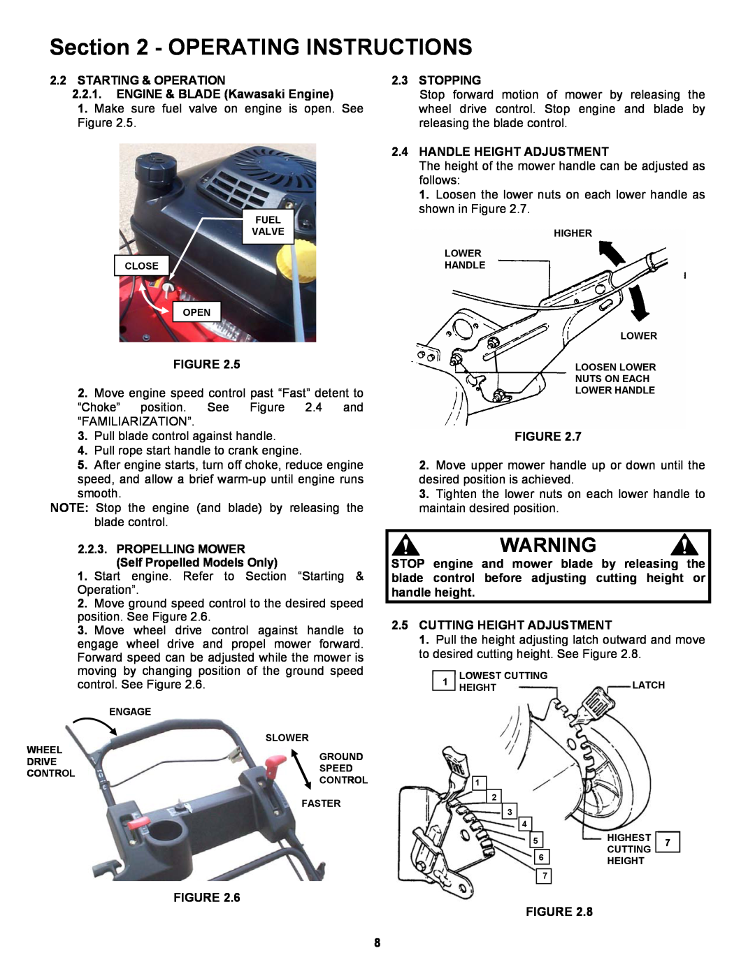
2.2 STARTING & OPERATION 2.2.1. ENGINE & BLADE Briggs Engine
Section 2 - OPERATING INSTRUCTIONS
2.1 PRE-START CHECK LIST
2.4 HANDLE HEIGHT ADJUSTMENT
2.5 CUTTING HEIGHT ADJUSTMENT
2.2 STARTING & OPERATION 2.2.1. ENGINE & BLADE Kawasaki Engine
2.3 STOPPING
FIGURE 2.10a
2.6 INSTALLATION of GRASS BAG ADAPTER
2.7 INSTALLATION of RECYCLING PLUG Optional Accessory on Some Models
Attach grass bag hooks over middle handle cross bar See Figure
1. Set all wheels in the highest cutting position Notch
Section 3 - MAINTENANCE
3.2.3. CHECK MOWER BLADE
Section 4 - REPAIR & ADJUSTMENTS
4. Sharpen blade on a grinding wheel at an angle of
1. Grease on drive disc causing slippage
7. Reinstall driven disc spring to driven disc assembly
Section 4 - REPAIR & ADJUSTMENTS
To replace the bearing on the pulley end of the hex
Remove the driven disc. Refer to Section
Methods of Checking Battery Condition
TROUBLESHOOTING
PROBLEM
PROBABLE CAUSE
CORRECTIVE ACTION
SERVICE SCHEDULE
MAINTENANCE PARTS
2 YEAR LIMITED WARRANTY
PRIMARY MAINTENANCE
PRIMARY MAINTENANCE
PRIMARY MAINTENANCE
PRIMARY MAINTENANCE
SNAPPER PRODUCT REGISTRATION FORM
Page
Page
21” STEEL DECK WALK BEHIND MOWERS SERIES
Top
Page
Image
Contents