7600036 BRAKE KIT FOR
SNAPPER & SIMPLICITY RZT/JAVELIN RIDING MOWERS
! | WARNING | ! |
DO NOT attempt any adjustments, maintenance, repairs, or service with engine running. Stop engine. Engage parking brake. Remove key. Remove spark plug wire and secure wire away from spark plug. Engine, muffler and surrounding areas are extremely hot. Avoid serious burns; allow components to cool down before installing kit. Replace worn or damaged parts prior to operating. Use approved fuel container. DO NOT smoke near open fuel container. DO NOT fill fuel tank indoors or when engine is running. Allow engine to cool for at least ten minutes before refilling. Make sure that fuel cap is tightened securely. Wipe off any spilled fuel before starting engine.
STEP 1:
a. Raise and block the rear of the machine to gain access to the transmissions on the underside of the machine.
b. With the machine securely blocked, move the motion control levers in from their neutral lock positions, in order to disengage the parking brake.
! | WARNING | ! |
Failure to securely block the machine may result in severe personal injury or equipment damage.
STEP 2:
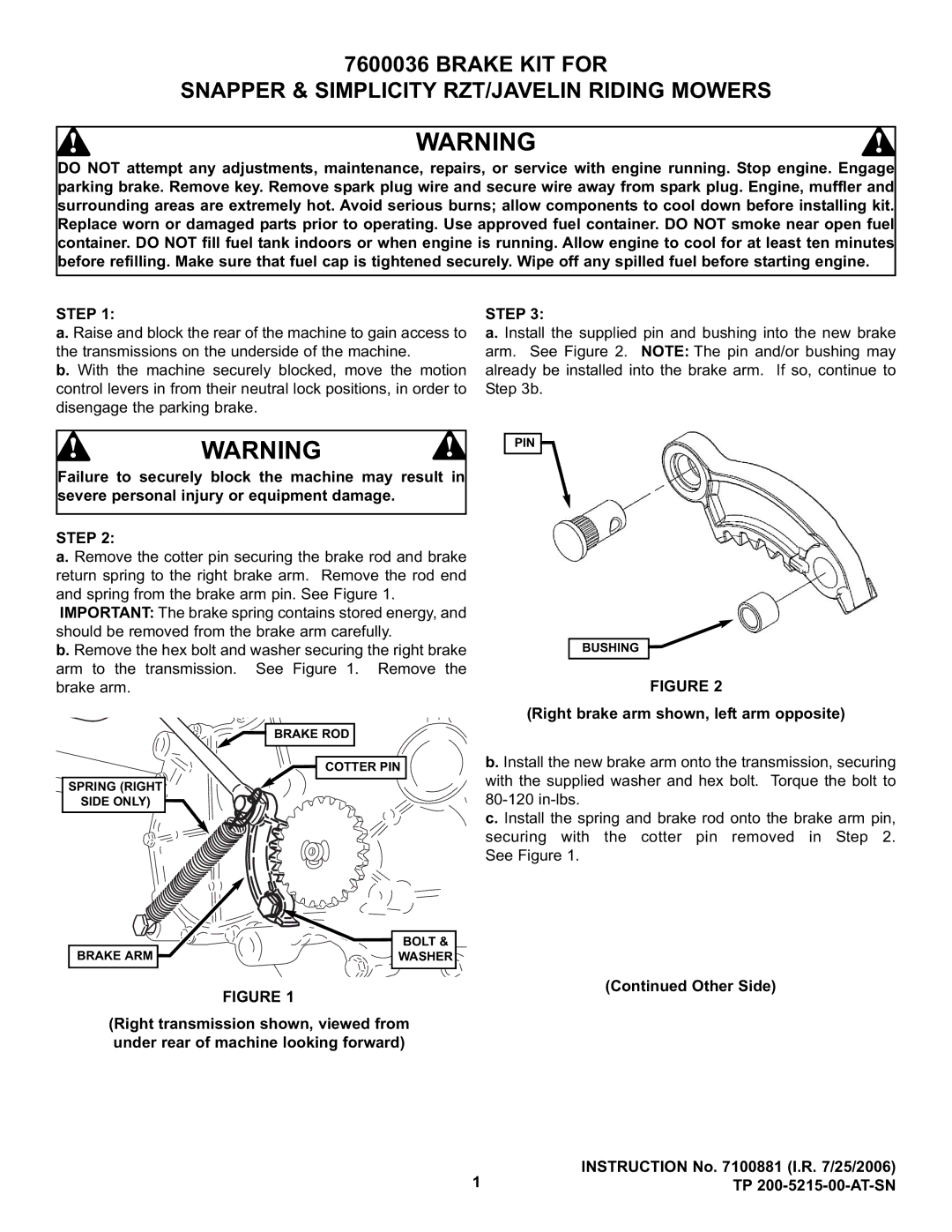
a. Remove the cotter pin securing the brake rod and brake return spring to the right brake arm. Remove the rod end and spring from the brake arm pin. See Figure 1.
IMPORTANT: The brake spring contains stored energy, and should be removed from the brake arm carefully.
b. Remove the hex bolt and washer securing the right brake arm to the transmission. See Figure 1. Remove the brake arm.
BRAKE ROD
COTTER PIN
SPRING (RIGHT
SIDE ONLY)
STEP 3:
a. Install the supplied pin and bushing into the new brake arm. See Figure 2. NOTE: The pin and/or bushing may already be installed into the brake arm. If so, continue to Step 3b.
PIN
BUSHING
FIGURE 2
(Right brake arm shown, left arm opposite)
b. Install the new brake arm onto the transmission, securing with the supplied washer and hex bolt. Torque the bolt to
c. Install the spring and brake rod onto the brake arm pin, securing with the cotter pin removed in Step 2. See Figure 1.
BRAKE ARM
BOLT &
WASHER
FIGURE 1
(Continued Other Side)
(Right transmission shown, viewed from under rear of machine looking forward)
| INSTRUCTION No. 7100881 (I.R. 7/25/2006) |
1 | TP |
