Manuals
/
Snapper
/
Lawn and Garden
/
Snow Blower
Snapper
11532, 9524, 9560, 1390, 1338, 11570, 1380, 10560, 10528 Adjustments, Traction Drive Tension
Models:
10528
10560
11532
1380
11570
1338
1390
9560
9524
1
24
32
32
Download
32 pages
5.15 Kb
21
22
23
24
25
26
27
28
Troubleshooting
Specification
Maintenance
Parts & Accessories
Adjustments
Shear Pin Replacement
Safety
Service
Features & Controls
Page 24
Image 24
Page 23
Page 25
Page 24
Image 24
Page 23
Page 25
Contents
OPERATOR’S MANUAL
Large Frame Snowthrowers
Table of Contents
CONTENTS
Regular Maintenance
Safety Rules & Information
Safety Rules & Information
TRAINING
PREPARATION
OPERATION
Safety Rules
SERVICE, MAINTENANCE, AND STORAGE
CHILDREN
CLEARING A CLOGGED DISCHARGE CHUTE
Page
Decals
DECALS
NORTH AMERICAN MODEL DECALS
CE MODEL DECALS
Safety Icons
SAFETY ICONS
Identification Numbers
CE IDENTIFICATION TAG MARKINGS
Identification Numbers
CE Models Place copy of Identification Tag here
Features, Controls, & Operation
CONTROL LOCATIONS
1,2.. Speed Selector
Traction Control / Free Hand Lock
Features & Controls
Operation
GENERAL OPERATION
DANGER
CHECKS BEFORE EACH START-UP
STARTING CONTROLS
STARTING THE ENGINE
Operation
Connect this extension cord ONLY to a properly
OPERATING THE SNOWTHROWER
CLEARING A CLOGGED DISCHARGE CHUTE
GROUND SPEED SELECTOR
ENGINE SPEED
DEFLECTOR
SCRAPER BAR & SKID SHOES
A B Figure 3. Chute Deflector Adjustment Some Models
Figure 5. Skid Shoe Adjustment A. Scraper Bar B. Skid Shoe C. Nuts
Operation
FULL TRACTION
EASY TURN TRACTION
EASY TURN FREEWHEELING AND TRACTION DRIVE LOCK
Storage
AFTER EACH USE
STORAGE
Regular Maintenance
MAINTENANCE SCHEDULE
CHECKING TIRE PRESSURE
AUGER GEAR CASE LUBRICATION
Regular Maintenance
LUBRICATION
LUBRICATING THE AUGER SHAFT & ASSEMBLY
CHECK / LUBRICATE FREE-HAND LINKAGE
Page
Troubleshooting, Adjustments, Service
TROUBLESHOOTING
Troubleshooting
Adjustments
SPEED SELECTOR ADJUSTMENT
AUGER DRIVE TENSION
Adjustments
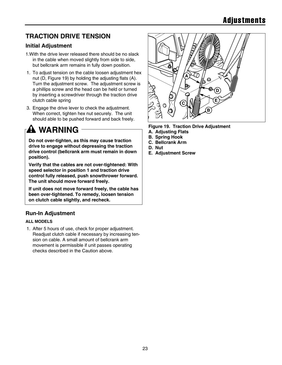
TRACTION DRIVE TENSION
MANUAL DISCHARGE CHUTE CONTROL LINKAGE ADJUSTMENT
ELECTRIC DISCHARGE CHUTE ROTATOR MOTOR ADJUSTMENT
Pinion Gear Adjustment
Gear Bracket Adjustment
Adjustments & Service
EASY TURN CABLE ADJUSTMENT
SHEAR PIN REPLACEMENT
BELT REPLACEMENT
Service
Specifications
DIMENSIONS
ENGINE
CHASSIS
Parts & Accessories
REPLACEMENT PARTS
MAINTENANCE ITEMS
TECHNICAL MANUALS
Top
Page
Image
Contents