Section 3 - ADJUSTMENTS & REPAIR

HANDLEBAR

Thoroughly clean all external surfaces and tines before storing the Tiller. The Tiller may be stored on end, however, the following steps must be taken:

DASH PANEL

LOOSEN

JAM NUTS

CLUTCH CABLE

STEP 1: Drain gasoline from fuel system and drain the engine crankcase oil (refer to engine manual for details). STEP 2: After standing the Tiller on end, check the plugs in the chain case for leakage. After extended period, some grease may seep through upper bearing races. STEP 3: Remove both wheels and grease wheel shafts. Reinstall wheels. Remove both tines and grease tine shafts. Reinstall tines. Grease these shafts when tiller is stored for long periods to prevent rust buildup. Rust

MOVE NUTS

TOWARD END

OF CABLE FOR

MORE TENSION

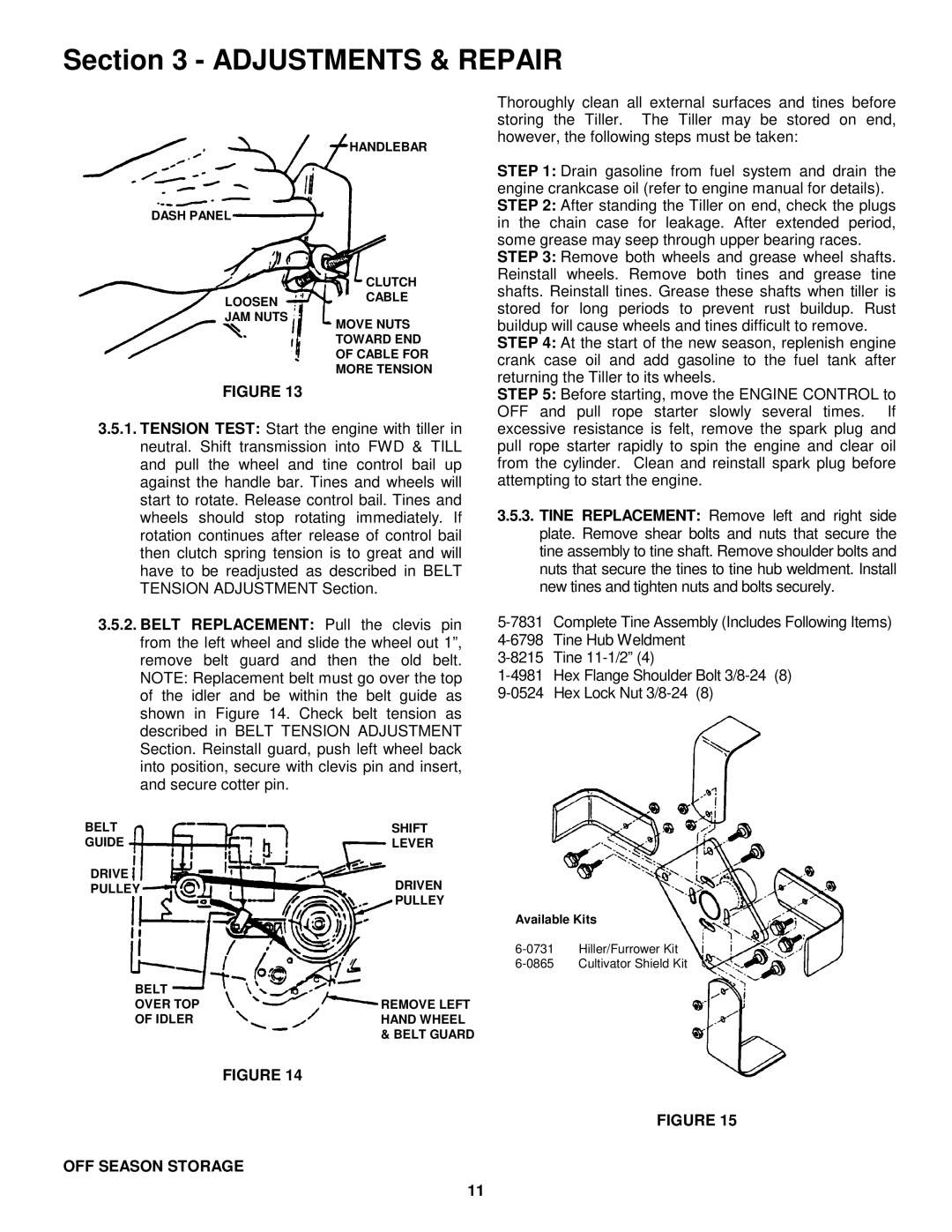
FIGURE 13

3.5.1.TENSION TEST: Start the engine with tiller in neutral. Shift transmission into FWD & TILL and pull the wheel and tine control bail up against the handle bar. Tines and wheels will start to rotate. Release control bail. Tines and wheels should stop rotating immediately. If rotation continues after release of control bail then clutch spring tension is to great and will have to be readjusted as described in BELT TENSION ADJUSTMENT Section.

3.5.2.BELT REPLACEMENT: Pull the clevis pin from the left wheel and slide the wheel out 1”, remove belt guard and then the old belt. NOTE: Replacement belt must go over the top of the idler and be within the belt guide as shown in Figure 14. Check belt tension as described in BELT TENSION ADJUSTMENT Section. Reinstall guard, push left wheel back into position, secure with clevis pin and insert, and secure cotter pin.

BELT

SHIFT

GUIDE

LEVER

DRIVE

DRIVEN

PULLEY


PULLEY

BELT


OVER TOP

REMOVE LEFT

OF IDLER

HAND WHEEL


& BELT GUARD

buildup will cause wheels and tines difficult to remove. STEP 4: At the start of the new season, replenish engine crank case oil and add gasoline to the fuel tank after returning the Tiller to its wheels.

STEP 5: Before starting, move the ENGINE CONTROL to OFF and pull rope starter slowly several times. If excessive resistance is felt, remove the spark plug and pull rope starter rapidly to spin the engine and clear oil from the cylinder. Clean and reinstall spark plug before attempting to start the engine.

3.5.3.TINE REPLACEMENT: Remove left and right side plate. Remove shear bolts and nuts that secure the tine assembly to tine shaft. Remove shoulder bolts and nuts that secure the tines to tine hub weldment. Install new tines and tighten nuts and bolts securely.

5-7831 Complete Tine Assembly (Includes Following Items)

4-6798 Tine Hub Weldment

3-8215 Tine 11-1/2” (4)

1-4981 Hex Flange Shoulder Bolt 3/8-24 (8)

9-0524 Hex Lock Nut 3/8-24 (8)

Available Kits

6-0731 Hiller/Furrower Kit

6-0865 Cultivator Shield Kit

FIGURE 14

FIGURE 15

OFF SEASON STORAGE

11

Page 11
Image 11
Snapper EICFR5004B important safety instructions OFF Season Storage

EICFR5004B specifications

The Snapper EICFR5004B is a versatile and reliable riding lawn mower designed for homeowners who demand performance and efficiency in their lawn care routine. This mower is engineered to provide a smooth, clean cut while ensuring ease of use and comfort during operation.

One of the standout features of the Snapper EICFR5004B is its powerful engine. It is equipped with a robust 500cc Briggs & Stratton engine that delivers reliable starting and plenty of power for tackling tough grass and uneven terrain. The engine is designed for efficiency, allowing users to complete their mowing tasks quickly, even on larger lawns.

The cutting system of the EICFR5004B is another highlight. The mower boasts a 42-inch cutting deck that provides a wide cutting path, reducing the number of passes needed to achieve a pristine lawn. The deck is constructed from durable materials, ensuring longevity and resistance to wear and tear. Additionally, it features a six-position height adjustment lever, which allows users to easily customize cutting heights between 1.5 inches and 4 inches to suit their lawn’s specific needs.

Comfort is a key consideration in the design of the Snapper EICFR5004B. The mower features an ergonomic seat with ample cushioning, providing a comfortable riding experience over extended periods. The controls are intuitively placed and easy to reach, allowing users to operate the mower without strain. The compact design also makes it easy to maneuver in tight spaces, such as around flower beds and trees.

Another significant technology integrated into the Snapper EICFR5004B is its SmartSpeed control system. This innovative feature allows users to control their speed with precision. It provides three different speed ranges for trimming, towing, and mowing, making it versatile for various tasks. This means users can adjust their speed without compromising on cutting performance or efficiency.

Maintenance is simplified with the EICFR5004B as well. The mower is designed with a removable deck, making it easy to clean and service. The engine compartment is also accessible, allowing users to perform routine maintenance tasks without extensive effort.

In conclusion, the Snapper EICFR5004B is built for performance, comfort, and convenience. With its powerful engine, versatile cutting system, and innovative speed control technology, it is well-suited for homeowners seeking a reliable riding mower that effaces the complexities of lawn maintenance. Its combination of features makes mowing not only easier but also more enjoyable, setting a new standard in residential lawn care solutions.