Section 3 - ADJUSTMENTS & REPAIR
3.3.2.ADD LUBRICATION TO CHAIN CASE: To add grease, remove the filler plug located just forward of the pulley shaft on the right hand side. See Figure 10. Add Snapper Part No.
CHAIN
CASE
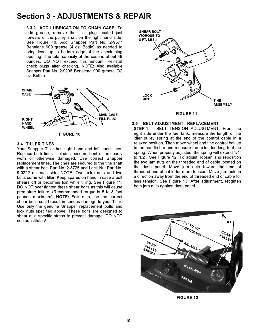
SHEAR BOLT (TORQUE TO 8 FT. LBS.)
LOCK
NUT
TINE ASSEMBLY
MAIN CASE
RIGHTFILL PLUG HAND
WHEEL
FIGURE 10
3.4 TILLER TINES
Your Snapper Tiller has right hand and left hand tines. Replace both tines if blades become bent or are badly worn or otherwise damaged. Use correct Snapper replacement tines. The tines are secured to the tine shaft with a shear bolt, Part No.
FIGURE 11
3.5BELT ADJUSTMENT - REPLACEMENT
STEP 1: BELT TENSION ADJUSTMENT: From the right side under the fuel tank, measure the length of the idler pulley spring at the end of the control cable in a relaxed position. Then move wheel and tine control bail up to the handle bar and measure the extended length of the spring. When properly adjusted, the spring will extend 1/4” to 1/2”. See Figure 12. To adjust, loosen and reposition the two jam nuts on the threaded end of cable located on the dash panel. Move jam nuts toward the end of threaded end of cable for more tension. Move jam nuts in a direction away from the end of threaded end of cable for less tension. See Figure 13. After adjustment, retighten both jam nuts against dash panel.
BELT
FIGURE 12
10