Manuals
/
Snapper
/
Lawn and Garden
/
Lawn Mower
Snapper
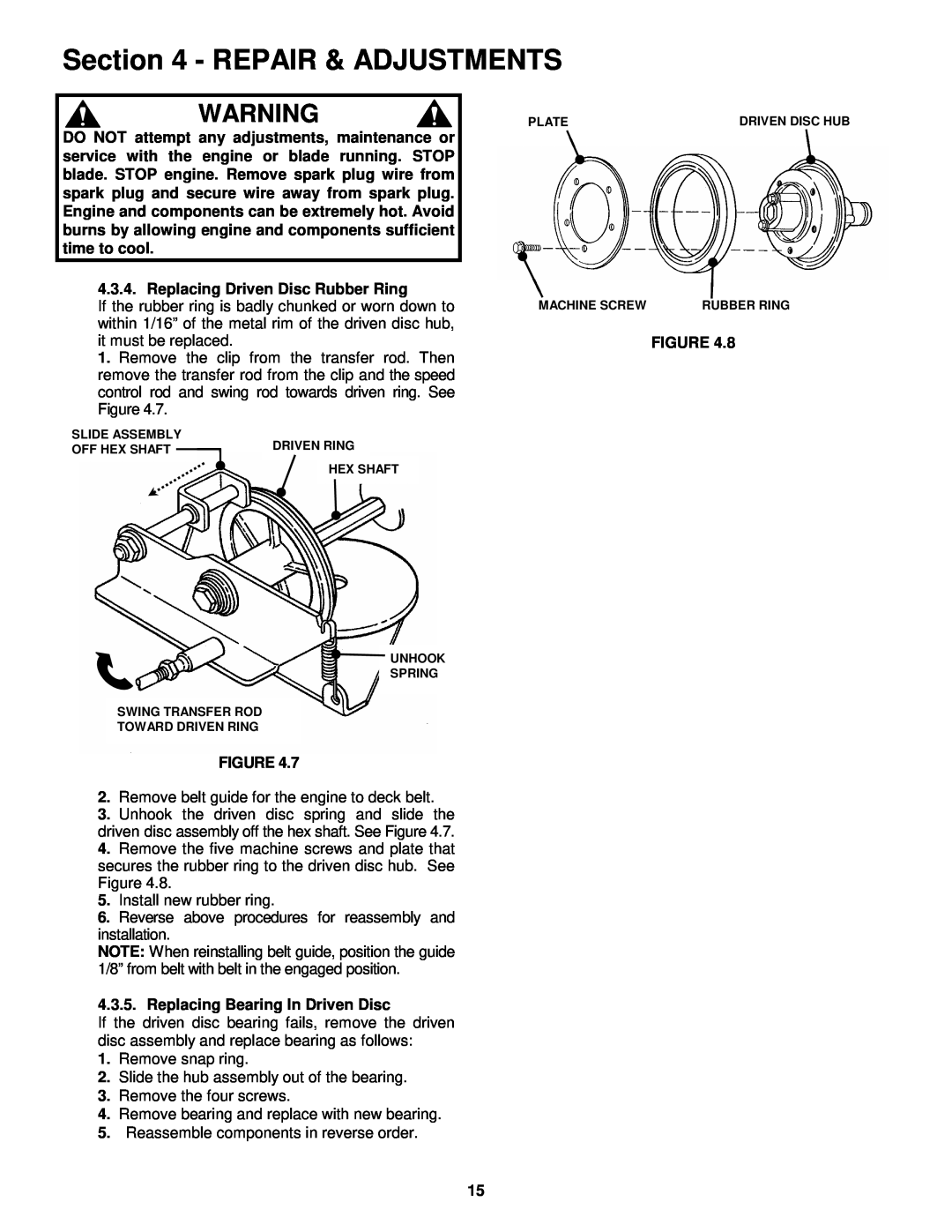
HWPS26600RV Repair & Adjustments, Remove belt guide for the engine to deck belt
Models:
HWPS26600RV
1
15
28
28
Download
28 pages
17.24 Kb
12
13
14
15
16
17
18
19
Troubleshooting
Warranty
Maintenance
Handle Height Adjustment
Safety
Service Schedule
Page 15
Image 15
Page 14
Page 16
Page 15
Image 15
Page 14
Page 16
Contents
MANUAL No. 4-6813 REV. 1, 8/25/99
Safety Instructions & Operator’s Manual for
MODEL
MODEL NUMBER EXPLANATION
PREPARATION
IMPORTANT SAFETY INSTRUCTIONS
PROTECTION FOR CHILDREN
SLOPE OPERATION
OPERATION
MAINTENANCE AND STORAGE
12-18
TABLE OF CONTENTS
Transmission Poly-V Belt Tension Adjustment
10-11
Section 1 - FAMILIARIZATION
1.1 INTRODUCTION
1.2 NOMENCLATURE
DO NOT park machine on slopes
Section 2 - OPERATING INSTRUCTIONS
2.1 PRE-START CHECK LIST
while the engine is running
2.3 STOPPING 2.3.1. WHEEL DRIVE
2.2 STARTING & OPERATION
2.2.2. BLADE
2.2.3. PROPELLING MOWER WHEEL DRIVE
2.4 HANDLE HEIGHT ADJUSTMENT
2.7 RECYCLING OPERATION OPTIONAL
2.6 SWIVEL WHEEL LOCK and UNLOCK
Section 3 - MAINTENANCE
3.2 SERVICE - AFTER FIRST 5 HOURS Continued From Previous Page
WEAR LIMIT NOTCH STARTS END VIEW OF BLADE
Section 4 - REPAIR & ADJUSTMENTS
NEW BLADE
REMOVE BLADE RETAINING BOLTS TO REMOVE BLADE
1. Stop engine and allow sufficient time to cool
1. Loosen jam nut from ball joint on transfer rod
2. Remove belt guide for the engine to deck belt
3. Remove holder, O-ring and bearing 4. Install new bearing
4. Slip belt off of belt idler 5. Remove belt from hex shaft pulley
1. Remove spindle cover
CORRECTIVE ACTION
TROUBLESHOOTING
PROBLEM
PROBABLE CAUSE
SERVICE SCHEDULE
3 YEAR LIMITED WARRANTY
PRIMARY MAINTENANCE
PRIMARY MAINTENANCE
PRIMARY MAINTENANCE
PRIMARY MAINTENANCE
SERVICE NOTES
SERVICE NOTES
26” STEEL DECK WALK MOWERS SERIES
Top
Page
Image
Contents