Snapper SPE131KW, SPE361, SPE481 Operating Instructions, Adjusting Fixed Deck Attachment

Models: SPE131KW, SPE361, SPE481

1 35
Download 35 pages 25.96 Kb
Page 16
Image 16
3.12ADJUSTING BLADE ON CUTTER SPINDLE (Continued)

SECTION 3 - OPERATING INSTRUCTIONS

3.12ADJUSTING BLADE ON CUTTER SPINDLE (Continued)

CUTTER

SPACERS

ON TOP

HOUSING

PULLEY


CUTTER


HOUSING

BLADE

SPACERS ON


BOTTOM


FIGURE 3.14

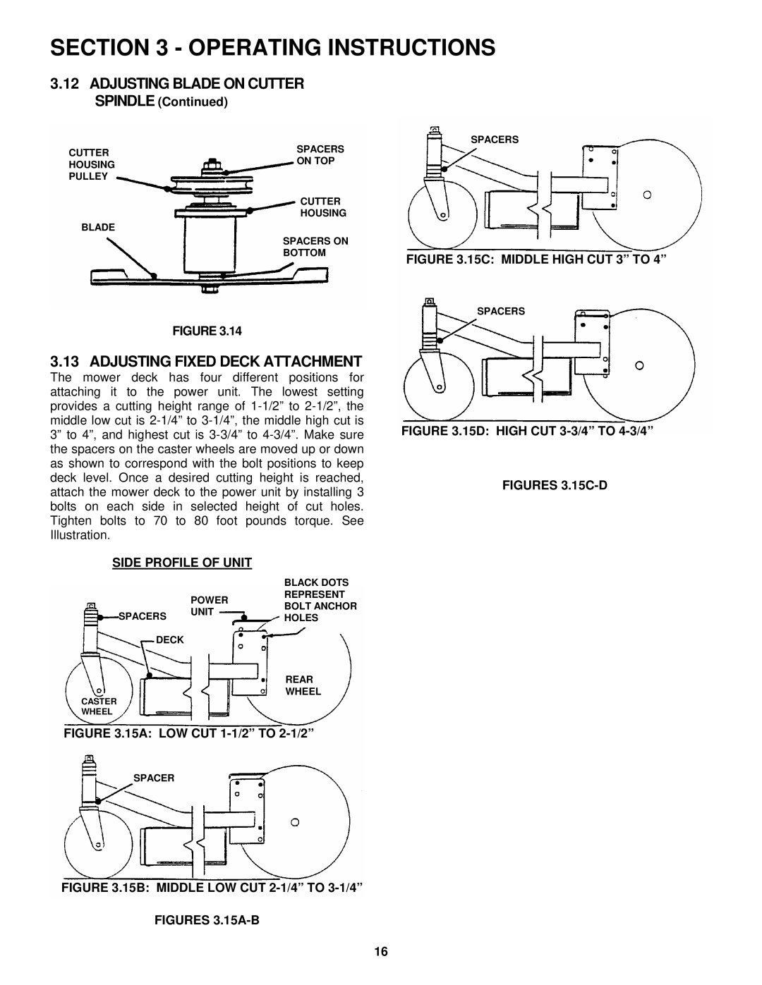
3.13 ADJUSTING FIXED DECK ATTACHMENT

The mower deck has four different positions for attaching it to the power unit. The lowest setting provides a cutting height range of 1-1/2” to 2-1/2”, the middle low cut is 2-1/4” to 3-1/4”, the middle high cut is 3” to 4”, and highest cut is 3-3/4” to 4-3/4”. Make sure the spacers on the caster wheels are moved up or down as shown to correspond with the bolt positions to keep deck level. Once a desired cutting height is reached, attach the mower deck to the power unit by installing 3 bolts on each side in selected height of cut holes. Tighten bolts to 70 to 80 foot pounds torque. See Illustration.

SIDE PROFILE OF UNIT

BLACK DOTS

POWERREPRESENT

SPACERS UNITBOLT ANCHOR HOLES

DECK

REAR

WHEEL

CASTER

WHEEL

FIGURE 3.15A: LOW CUT 1-1/2” TO 2-1/2”

SPACERS

FIGURE 3.15C: MIDDLE HIGH CUT 3” TO 4”

SPACERS

FIGURE 3.15D: HIGH CUT 3-3/4” TO 4-3/4”

FIGURES 3.15C-D

SPACER

FIGURE 3.15B: MIDDLE LOW CUT 2-1/4” TO 3-1/4”

FIGURES 3.15A-B

16

Page 16
Image 16
Snapper SPE131KW, SPE361, SPE481 Operating Instructions, ADJUSTING BLADE ON CUTTER SPINDLE Continued, Side Profile Of Unit