Section 4 - ADJUSTMENTS & REPAIR
4.2.1.MOWER DECK ADJUSTMENT (LEVELNESS) (Continued)
6.Loosen the nuts and bolts that secure both front and rear deck support brackets on the high side of deck. Located above each support bracket, on the top part of the power unit frame, are three shim plates. Remove the shim plates on both of the front and rear lift arms and position plates between the support bracket and the frame of the power unit. Inserting the shim plates in this procedure will lower that side of the deck. Retighten the support bracket nuts and bolts to
20to 30 ft. lbs. of torque. See Figure 4.2.
POWER
UNIT
FRAME
11.Place a wooden block under the front and rear edge of the mower deck.
12.Move deck lift lever and set the mower deck to a lower cutting position until deck rests on wooden blocks. This will relieve pressure from deck lift components.
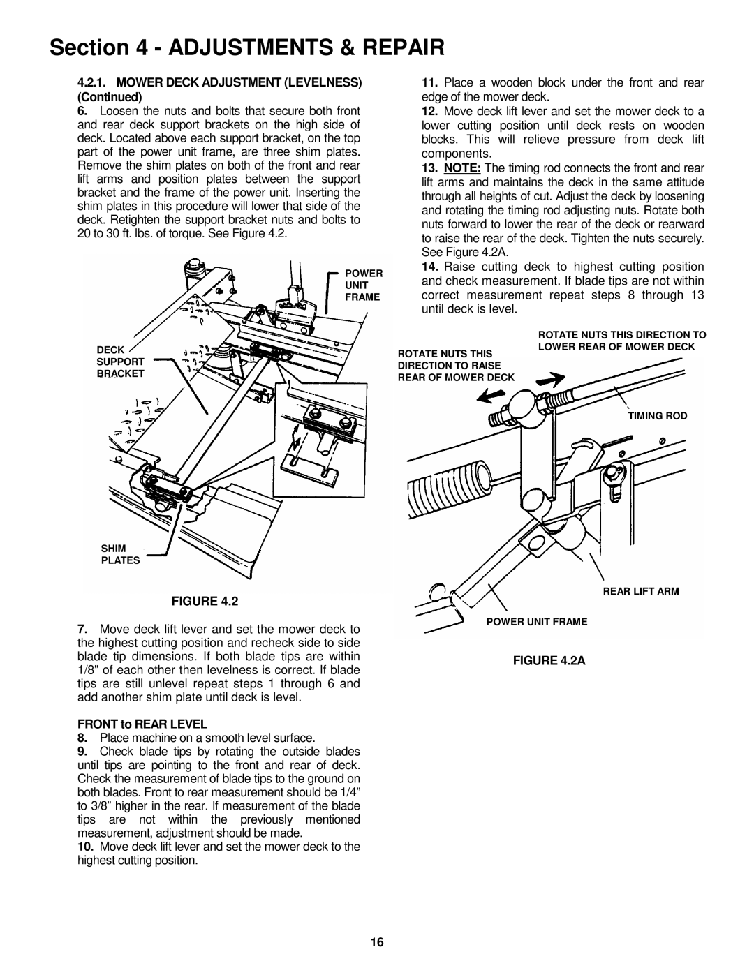
13.NOTE: The timing rod connects the front and rear lift arms and maintains the deck in the same attitude through all heights of cut. Adjust the deck by loosening and rotating the timing rod adjusting nuts. Rotate both nuts forward to lower the rear of the deck or rearward to raise the rear of the deck. Tighten the nuts securely. See Figure 4.2A.
14.Raise cutting deck to highest cutting position and check measurement. If blade tips are not within correct measurement repeat steps 8 through 13 until deck is level.
DECK
SUPPORT
BRACKET
SHIM
PLATES
FIGURE 4.2
ROTATE NUTS THIS DIRECTION TO RAISE REAR OF MOWER DECK
ROTATE NUTS THIS DIRECTION TO LOWER REAR OF MOWER DECK
TIMING ROD
REAR LIFT ARM
7.Move deck lift lever and set the mower deck to the highest cutting position and recheck side to side blade tip dimensions. If both blade tips are within 1/8” of each other then levelness is correct. If blade tips are still unlevel repeat steps 1 through 6 and add another shim plate until deck is level.
FRONT to REAR LEVEL
8.Place machine on a smooth level surface.
9.Check blade tips by rotating the outside blades until tips are pointing to the front and rear of deck. Check the measurement of blade tips to the ground on both blades. Front to rear measurement should be 1/4” to 3/8” higher in the rear. If measurement of the blade tips are not within the previously mentioned measurement, adjustment should be made.
10.Move deck lift lever and set the mower deck to the highest cutting position.
POWER UNIT FRAME
FIGURE 4.2A
16