K.4.2
K.4.3
| 4. | Switch BLK in and | |
| 5. | Adjust VR16 for +18dBu ±0.25dB. | |
| 6. | Reset LMF Gain to its centre indent position and release the BLK switch. | |
LF EQ – Maximum Gain |
| ||
1. | Ensure that the BLK switch is released. | ||
Adjustment: | |||
| 2. | Set LF Gain to maximum and select LF BELL. Set the audio oscillator for | |
|
| 80Hz and adjust LF Frequency to find the maximum level on the audio | |
| 3. | level meter. | |
| Adjust VR17 for +15dBu ±0.25dB. | ||
| 4. | Switch BLK in and | |
| 5. | Adjust VR18 for +18dBu ±0.25dB. | |
| 6. | Reset LF Gain to its centre indent position, release the BLK switch and de- | |
Output Balance |
| select LF BELL. | |
| Calibrated audio oscillator, audio level meter and a ‘balance’ adaptor (see | ||
Equipment Required: |
| ||
Test Signal: |
| below). | |
| 1kHz sine wave at +24dBu. | ||
Input and Output: |
| Oscillator to the Input of the channel being tested, Output to the level | |
Unit Setup: |
| meter via the ‘balance’ adaptor. | |
| Ensure that all front panel switches are off and all controls are set fully | ||
Adjustment: |
| ||
| Connect the test equipment to the each channel in turn and adjust VR19 | ||
|
| (BAL) for minimum level (< 55dBr). |
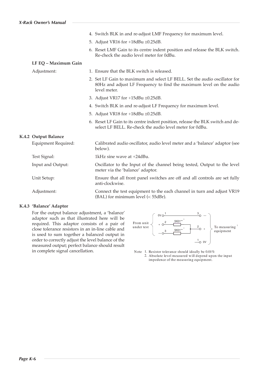
‘Balance’ Adaptor |
| 0V | 1 |
|
|
| 3 | – |
|
|
For the output balance adjustment, a ‘balance’ |
|
|
|
|
|
| ||||
adaptor such as that illustrated here will be |
|
|
| 5K01** | 1 |
|
|
|
| |
required. This adaptor consists of a pair of | From unit | + | 2 |
|
|
| 2 |
| To measuring | 2 |
|
|
|
| |||||||
close tolerance resistors in an | under test |
| 3 |
| ** | 1 |
| + |
| |
| 5K01 |
|
| |||||||
is used to sum together a balanced output in |
| – |
|
|
|
| 1 | 0V | equipment |
|
|
|
|
|
|
| |||||
|
|
|
|
|
| |||||
order to correctly adjust the level balance of the |
|
|
|
|
|
|
|
| ||
measured output; perfect balance should result | Note 1. | Resistor tolerance should ideally be 0.01% |
| |||||||
in complete signal cancellation. |
| |||||||||
| 2. | Absolute level measured will depend upon the input |
| |||||||
|
| impedence of the measuring equipment. |
|
| ||||||
Page