DDM-2810CSU, DDM-2800CSU specifications
The Sony DDM-2800CSU and DDM-2810CSU represent a significant advancement in digital video disc technology, tailored for professional and creative use. As part of the renowned Sony lineup, these models offer superior performance and reliability, making them ideal for various applications including video production, broadcasting, and archiving.One of the standout features of the DDM-2800CSU and DDM-2810CSU is their support for dual-layer recording, allowing users to store up to 8.5 GB of data on a single disc. This capability is crucial for professionals who require high-capacity storage for high-definition video content and large multimedia projects. The dual-layer technology ensures that users can archive longer recordings without needing to switch discs, facilitating seamless playback and editing.
Both models are equipped with advanced error correction algorithms that enhance data integrity and reduce the risk of corruption. This is particularly important in professional settings where the reliability of data playback is paramount. Users can trust that their valuable content will be preserved without compromise.
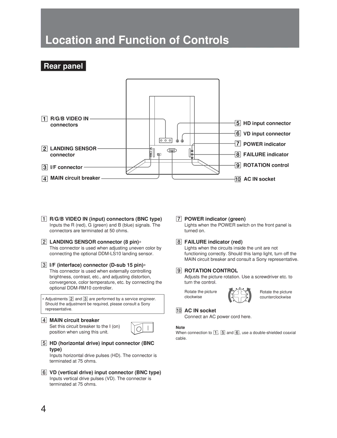
In terms of connectivity, the DDM-2800CSU and DDM-2810CSU feature versatile interface options including USB and Ethernet, enabling easy integration into existing workflows. This flexibility is essential for video editors and producers who are often required to connect multiple devices and systems to manage their projects efficiently.
The devices are designed with user-friendly operation in mind, featuring an intuitive interface that allows for quick access to features and functions. The LCD display provides clear information about disc status, remaining capacity, and recording time, making it easier for users to monitor their progress during sessions.
Moreover, both models utilize high-precision optical technology, ensuring that data retrieval and writing are executed with remarkable accuracy. This precision translates to minimal wear on discs and prolongs their lifespan, which is especially beneficial for archival purposes.
The DDM-2800CSU and DDM-2810CSU also offer compatibility with various media formats, making them a versatile choice for Multimedia professionals. With options for burning, reading, and authoring, these units stand out as multifunctional tools that cater to the diverse needs of today’s content creators.
In summary, the Sony DDM-2800CSU and DDM-2810CSU bring together cutting-edge technology and user-centric design. With their high-capacity storage, superior data integrity, flexible connectivity options, and robust performance, they are invaluable assets for professionals in the film and media industry looking to achieve excellence in their projects. These devices not only enhance productivity but also ensure that creative visions are efficiently captured and preserved for years to come.

