SECTION 6
DIAGRAMS
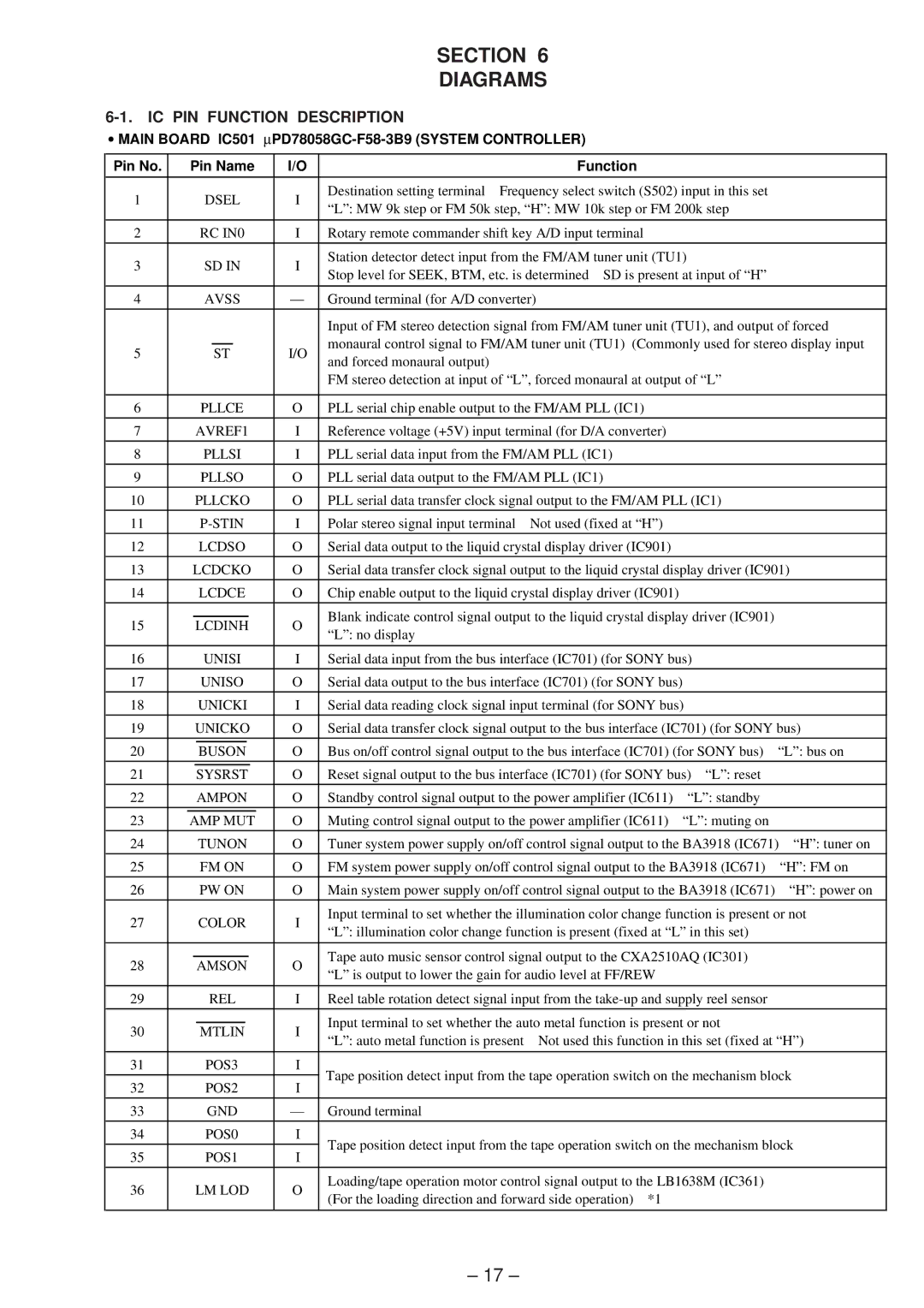
6-1. IC PIN FUNCTION DESCRIPTION
•MAIN BOARD IC501 ∝PD78058GC-F58-3B9 (SYSTEM CONTROLLER)
Pin No. |
| Pin Name | I/O |
| Function |
|
| |
|
|
|
|
|
|
| ||
1 |
| DSEL | I | Destination setting terminal Frequency select switch (S502) input in this set |
| |||
| “L”: MW 9k step or FM 50k step, “H”: MW 10k step or FM 200k step |
| ||||||
|
|
|
|
|
| |||
|
|
|
|
|
|
|
| |
2 |
| RC IN0 | I | Rotary remote commander shift key A/D input terminal |
|
| ||
|
|
|
|
|
|
| ||
3 |
| SD IN | I | Station detector detect input from the FM/AM tuner unit (TU1) |
| |||
| Stop level for SEEK, BTM, etc. is determined SD is present at input of “H” |
| ||||||
|
|
|
|
|
| |||
|
|
|
|
|
|
|
| |
4 |
| AVSS | — | Ground terminal (for A/D converter) |
|
| ||
|
|
|
|
| Input of FM stereo detection signal from FM/AM tuner unit (TU1), and output of forced | |||
5 |
| ST | I/O | monaural control signal to FM/AM tuner unit (TU1) (Commonly used for stereo display input | ||||
| and forced monaural output) |
|
|
| ||||
|
|
|
|
|
|
|
| |
|
|
|
|
| FM stereo detection at input of “L”, forced monaural at output of “L” |
| ||
|
|
|
|
|
|
|
| |
6 |
| PLLCE | O | PLL serial chip enable output to the FM/AM PLL (IC1) |
|
| ||
|
|
|
|
|
|
|
| |
7 |
| AVREF1 | I | Reference voltage (+5V) input terminal (for D/A converter) |
|
| ||
8 |
| PLLSI | I | PLL serial data input from the FM/AM PLL (IC1) |
|
| ||
9 |
| PLLSO | O | PLL serial data output to the FM/AM PLL (IC1) |
|
| ||
|
|
|
|
|
|
| ||
10 |
| PLLCKO | O | PLL serial data transfer clock signal output to the FM/AM PLL (IC1) |
| |||
|
|
|
|
|
|
|
|
|
11 |
| I | Polar stereo signal input terminal | Not used (fixed at “H”) |
|
| ||
|
|
|
|
|
|
|
| |
12 |
| LCDSO | O | Serial data output to the liquid crystal display driver (IC901) |
|
| ||
|
|
|
|
|
| |||
13 |
| LCDCKO | O | Serial data transfer clock signal output to the liquid crystal display driver (IC901) | ||||
14 |
| LCDCE | O | Chip enable output to the liquid crystal display driver (IC901) |
|
| ||
|
|
|
|
|
|
| ||
15 |
| LCDINH | O | Blank indicate control signal output to the liquid crystal display driver (IC901) |
| |||
| “L”: no display |
|
|
| ||||
|
|
|
|
|
|
|
| |
|
|
|
|
|
| |||
16 |
| UNISI | I | Serial data input from the bus interface (IC701) (for SONY bus) |
| |||
|
|
|
|
|
|
| ||
17 |
| UNISO | O | Serial data output to the bus interface (IC701) (for SONY bus) |
|
| ||
|
|
|
|
|
| |||
18 |
| UNICKI | I | Serial data reading clock signal input terminal (for SONY bus) |
| |||
|
|
|
|
| ||||
19 |
| UNICKO | O | Serial data transfer clock signal output to the bus interface (IC701) (for SONY bus) | ||||
|
|
|
|
|
|
| ||
20 |
| BUSON | O | Bus on/off control signal output to the bus interface (IC701) (for SONY bus) | “L”: bus on | |||
|
|
|
|
|
|
| ||
21 |
| SYSRST | O | Reset signal output to the bus interface (IC701) (for SONY bus) “L”: reset |
| |||
|
|
|
|
|
|
|
| |
22 |
| AMPON | O | Standby control signal output to the power amplifier (IC611) | “L”: standby |
| ||
|
|
|
|
|
|
|
| |
23 |
| AMP MUT | O | Muting control signal output to the power amplifier (IC611) | “L”: muting on |
| ||
|
|
|
|
|
| |||
24 |
| TUNON | O | Tuner system power supply on/off control signal output to the BA3918 (IC671) “H”: tuner on | ||||
|
|
|
|
|
| |||
25 |
| FM ON | O | FM system power supply on/off control signal output to the BA3918 (IC671) | “H”: FM on | |||
26 |
| PW ON | O | Main system power supply on/off control signal output to the BA3918 (IC671) | “H”: power on | |||
27 |
| COLOR | I | Input terminal to set whether the illumination color change function is present or not | ||||
| “L”: illumination color change function is present (fixed at “L” in this set) |
| ||||||
|
|
|
|
|
| |||
|
|
|
|
|
|
| ||
28 |
| AMSON | O | Tape auto music sensor control signal output to the CXA2510AQ (IC301) |
| |||
| “L” is output to lower the gain for audio level at FF/REW |
|
| |||||
|
|
|
|
|
|
| ||
|
|
|
|
|
| |||
29 |
| REL | I | Reel table rotation detect signal input from the |
| |||
|
|
|
|
|
|
| ||
30 |
| MTLIN | I | Input terminal to set whether the auto metal function is present or not |
| |||
| “L”: auto metal function is present | Not used this function in this set (fixed at “H”) | ||||||
|
|
|
|
| ||||
|
|
|
|
|
|
|
| |
31 |
| POS3 | I | Tape position detect input from the tape operation switch on the mechanism block | ||||
32 |
| POS2 | I | |||||
|
|
|
|
| ||||
33 |
| GND | — | Ground terminal |
|
|
| |
34 |
| POS0 | I | Tape position detect input from the tape operation switch on the mechanism block | ||||
|
|
|
|
| ||||
35 |
| POS1 | I | |||||
|
|
|
|
| ||||
|
|
|
|
|
|
| ||
36 |
| LM LOD | O | Loading/tape operation motor control signal output to the LB1638M (IC361) |
| |||
| (For the loading direction and forward side operation) *1 |
|
| |||||
|
|
|
|
|
|
| ||
|
|
|
|
|
|
|
|
|
– 17 –