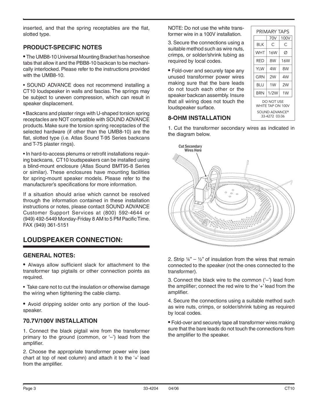
CT10 specifications
The Sound Tech CT10 is a versatile and powerful audio solution tailored for both professionals and audio enthusiasts. This compact and robust device boasts a unique combination of features and technologies that set it apart from competitors in its class.At the heart of the Sound Tech CT10 is its advanced digital signal processing (DSP) technology. This ensures high-fidelity sound quality by accurately processing audio signals and minimizing distortion. The CT10’s DSP allows users to customize equalization settings easily, enabling them to tailor the sound profile to suit various environments and preferences.
One of the standout characteristics of the CT10 is its user-friendly interface. The device features an intuitive control panel with a bright LCD display that provides real-time feedback on audio levels and settings. This makes it easy for users of all skill levels to navigate through the various functions and make adjustments quickly. The inclusion of programmable presets allows for instant recall of preferred settings, making transitions effortless in live performance scenarios.
The CT10 is designed with connectivity in mind. It offers multiple input options, including XLR, TRS, and RCA, allowing for seamless integration with various audio sources. Moreover, the device supports Bluetooth connectivity, enabling users to wirelessly stream audio from smartphones and tablets. This feature is particularly appreciated in modern settings where mobility and convenience are paramount.
Durability is another critical aspect of the Sound Tech CT10. Constructed with high-quality materials, it is built to withstand the rigors of both studio and live environments. Its compact size makes it highly portable, allowing it to be easily transported between locations.
Battery life is a vital consideration for any portable audio device, and the CT10 excels in this regard. With an extended battery life, users can rely on it for long recording sessions or performances without the worry of running out of power. For professionals, the inclusion of a quick-charge feature is a welcome addition, ensuring minimal downtime.
In conclusion, the Sound Tech CT10 embodies a blend of cutting-edge technology, ease of use, and durability. Its DSP capabilities, versatile connectivity options, user-friendly interface, and robust construction make it an ideal choice for anyone in need of a reliable audio solution, whether for professional use, home studios, or casual listening.

