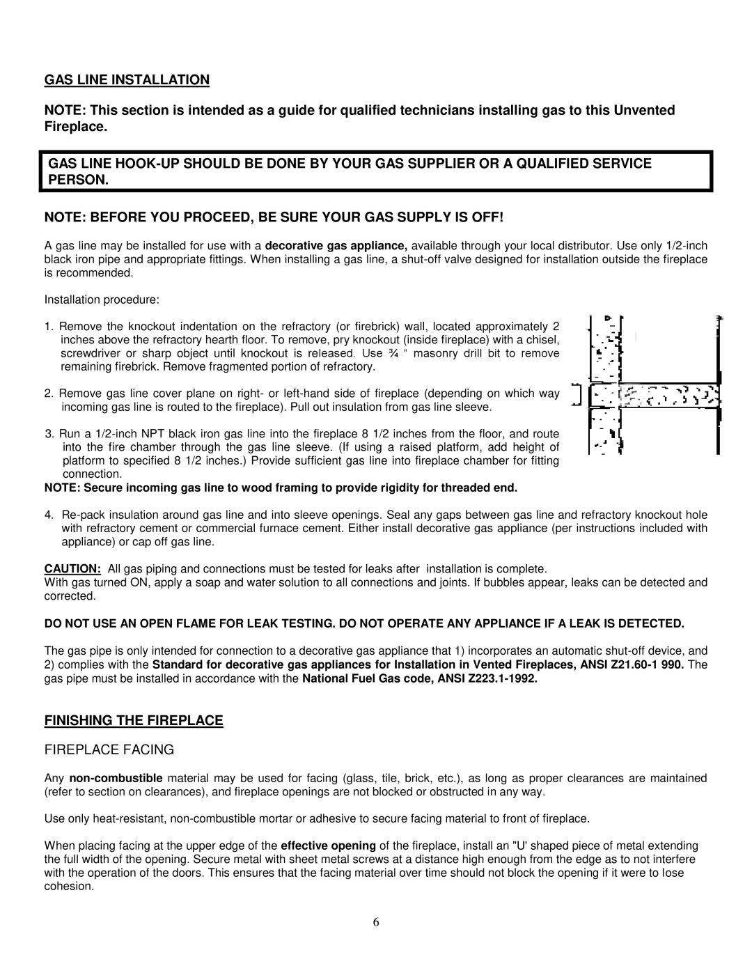
36, 42, 48 specifications
Southwest Specialty Products 48, 36, and 42 are innovative solutions designed to meet the diverse needs of various industries, including construction, manufacturing, and environmental management. These products showcase advanced technologies and practical features aimed at enhancing efficiency, safety, and performance in demanding environments.One of the standout features of the 48, 36, and 42 models is their robust construction. Made from high-grade materials, these products offer exceptional durability, ensuring long-lasting performance even under the toughest conditions. They are resistant to corrosion, which is crucial for applications in harsh environments, thus reducing maintenance costs and increasing operational lifespan.
The 48, 36, and 42 models also incorporate cutting-edge technology to optimize functionality. For instance, they are equipped with advanced chemical compatibility, enabling users to safely use a wide range of substances without fear of degradation. This characteristic is particularly beneficial for industries that handle hazardous materials, as it promotes safety and allows for more versatile applications.
Another key technological advancement is the incorporation of user-friendly designs. These models feature ergonomic handles and intuitive controls, making them easy to operate. This is crucial in environments where time efficiency is essential, as users can quickly adapt and utilize the equipment without extensive training.
In terms of size and capacity, the 48, 36, and 42 models cater to various requirements, allowing customization based on specific project needs. This flexibility makes them an excellent choice for contractors, engineers, and facility managers who require reliable and scalable solutions.
Furthermore, environmental considerations are integral to the design of Southwest Specialty Products. The 48, 36, and 42 models are engineered with eco-friendly practices in mind, promoting sustainability while maintaining high performance levels. This commitment to the environment is increasingly important in today's market, where businesses are held accountable for their environmental footprint.
In conclusion, Southwest Specialty Products 48, 36, and 42 stand out due to their robust construction, advanced technology, user-friendly designs, and environmental consciousness. These features make them ideal choices for professionals seeking reliable, efficient, and safe solutions in various high-demand industries.

