Step 5. Attach Connectors
This section tells how to connect internal peripherals and power supply to the Mainboard.
Internal peripherals include IDE devices (HDD,
For more details on how to connect internal and external peripherals to your new
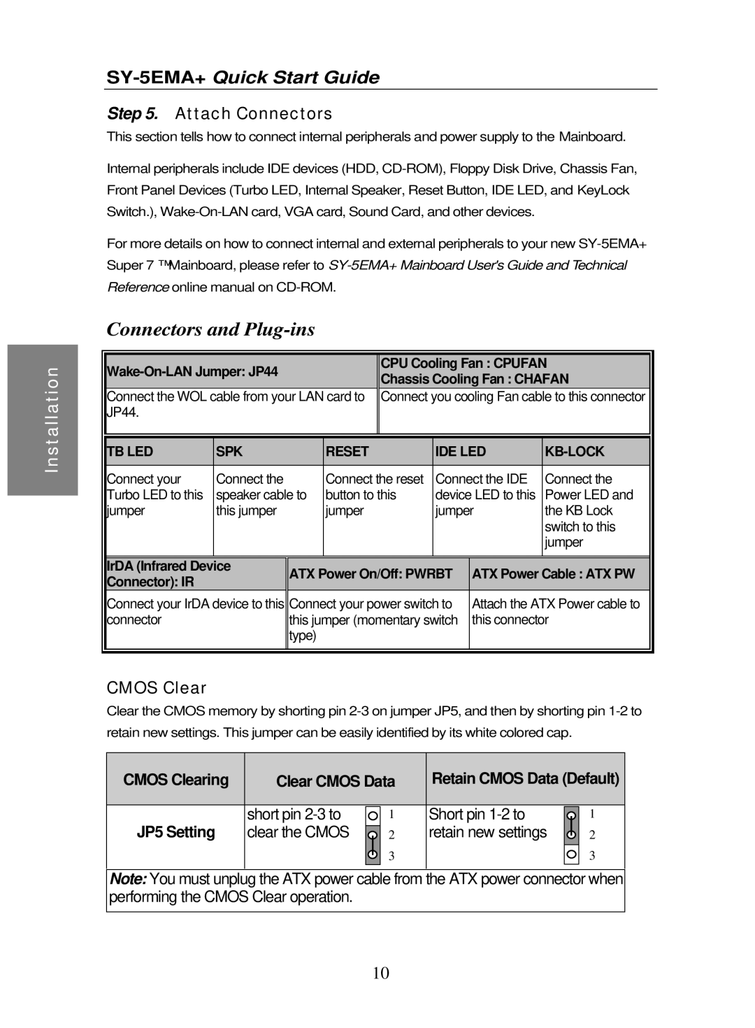
Connectors and Plug-ins
|
|
|
|
|
|
|
|
|
|
Installation |
|
|
| CPU Cooling Fan : CPUFAN | |||||
|
|
| Chassis Cooling Fan : CHAFAN | ||||||
|
|
|
| ||||||
|
|
|
|
|
| ||||
|
| Connect the WOL cable from your LAN card to | Connect you cooling Fan cable to this connector | ||||||
|
| JP44. |
|
|
|
|
|
|
|
|
|
|
|
|
|
|
|
|
|
|
|
|
|
|
|
|
|
| |
|
| TB LED | SPK |
| RESET | IDE LED |
| ||
|
|
|
|
|
|
|
|
| |
|
| Connect your | Connect the |
| Connect the reset | Connect the IDE | Connect the | ||
|
| Turbo LED to this | speaker cable to | button to this | device LED to this | Power LED and | |||
| |||||||||
|
| jumper | this jumper |
| jumper | jumper | the KB Lock | ||
|
|
|
|
|
|
|
|
| switch to this |
|
|
|
|
|
|
|
|
| jumper |
|
|
|
|
|
|
|
|
|
|
|
| IrDA (Infrared Device | ATX Power On/Off: PWRBT | ATX Power Cable : ATX PW | |||||
|
| Connector): IR |
| ||||||
|
|
|
|
|
|
|
|
| |
|
| Connect your IrDA device to this | Connect your power switch to | Attach the ATX Power cable to | |||||
|
| connector |
| this jumper (momentary switch | this connector | ||||
|
|
|
| type) |
|
|
|
|
|
|
|
|
|
|
|
|
|
|
|
|
|
|
|
|
|
|
|
|
|
CMOS Clear
Clear the CMOS memory by shorting pin
CMOS Clearing | Clear CMOS Data | Retain CMOS Data (Default) | ||||
|
|
|
|
|
|
|
| short pin |
| 1 | Short pin |
| 1 |
|
|
| ||||
JP5 Setting | clear the CMOS |
| 2 | retain new settings |
| 2 |
|
| |||||
| ||||||
|
|
| 3 |
|
| 3 |
|
|
|
| |||
|
|
|
|
|
|
|
Note: You must unplug the ATX power cable from the ATX power connector when performing the CMOS Clear operation.
10