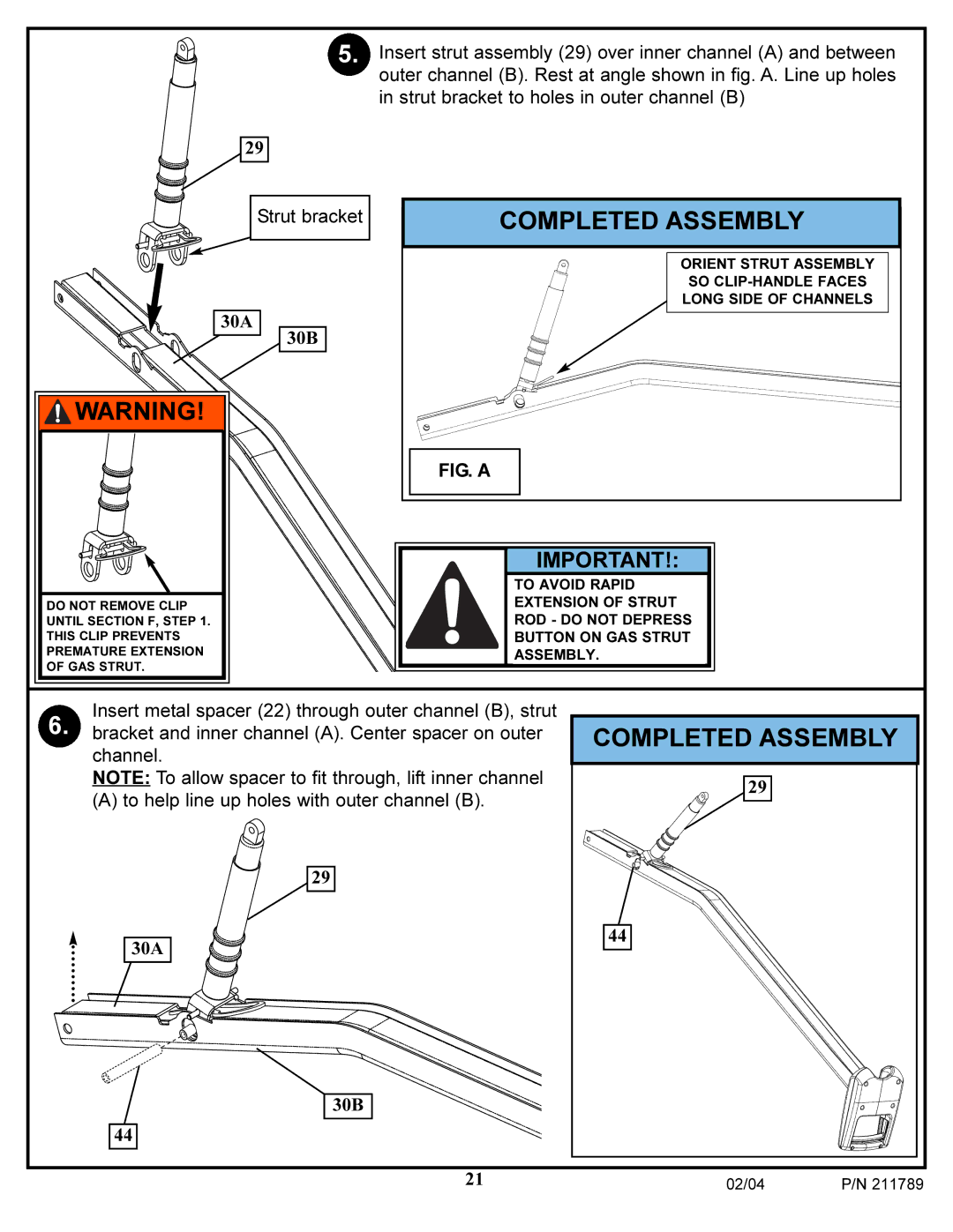
5. Insert strut assembly (29) over inner channel (A) and between outer channel (B). Rest at angle shown in fig. A. Line up holes in strut bracket to holes in outer channel (B)
29
Strut bracket
30A
30B
![]() WARNING!
WARNING!
DO NOT REMOVE CLIP
UNTIL SECTION F, STEP 1.
THIS CLIP PREVENTS
PREMATURE EXTENSION
OF GAS STRUT.
COMPLETED ASSEMBLY
ORIENT STRUT ASSEMBLY
SO
LONG SIDE OF CHANNELS
FIG. A
IMPORTANT!:
TO AVOID RAPID
EXTENSION OF STRUT
ROD - DO NOT DEPRESS
BUTTON ON GAS STRUT
ASSEMBLY.
Insert metal spacer (22) through outer channel (B), strut
6. bracket and inner channel (A). Center spacer on outer channel.
NOTE: To allow spacer to fit through, lift inner channel
(A) to help line up holes with outer channel (B).
29
30A
30B
44
COMPLETED ASSEMBLY
29
44
21 | 02/04 | P/N 211789 |
|