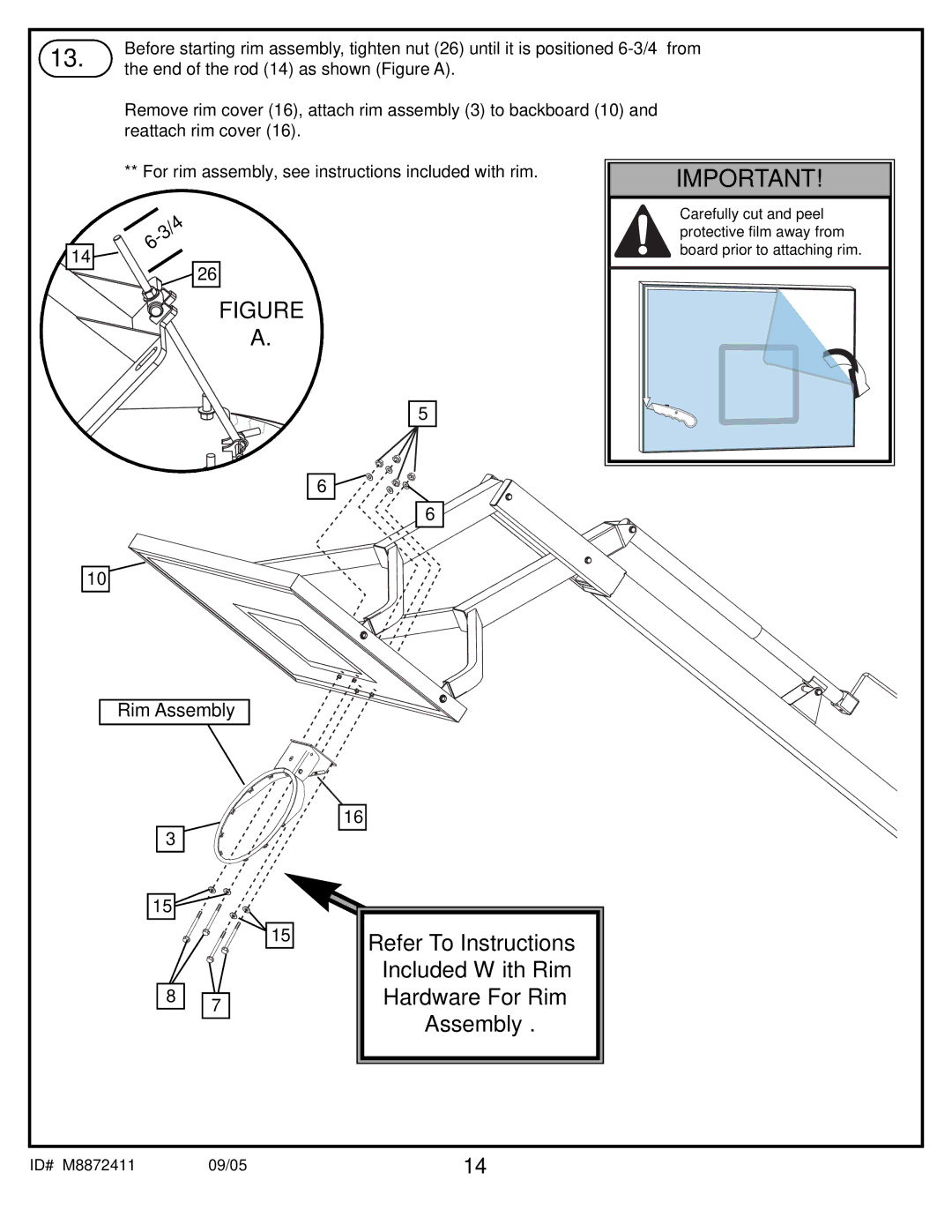
13. | Before starting rim assembly, tighten nut (26) until it is positioned | |
the end of the rod (14) as shown (Figure A). | ||
|
Remove rim cover (16), attach rim assembly (3) to backboard (10) and reattach rim cover (16).
** For rim assembly, see instructions included with rim.
14![]()
![]()
![]()
![]()
![]()
![]() 26
26
FIGURE
A.
5
6![]()
![]()
6
10
IMPORTANT!
Carefully cut and peel protective film away from board prior to attaching rim.
Rim Assembly
3
15
15
8 7
16
Refer To Instructions
Included With Rim
Hardware For Rim
Assembly.
ID# M8872411 | 09/05 | 14 |