OUTPUT SECTION
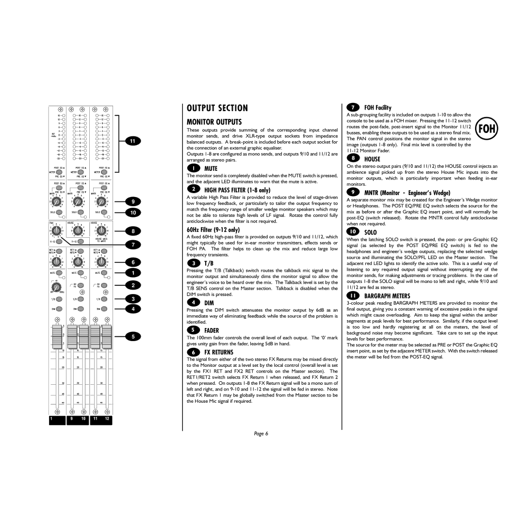
MONITOR OUTPUTS
These outputs provide summing of the corresponding input channel monitor sends, and drive XLR-type output sockets from impedance balanced outputs. A break-point is included before each output socket for the connection of an external graphic equaliser.
Outputs 1-8 are configured as mono sends, and outputs 9/10 and 11/12 are arranged as stereo pairs.
MUTE
The monitor send is completely disabled when the MUTE switch is pressed, and the adjacent LED illuminates to warn that the mute is active.
HIGH PASS FILTER (1-8 only)
A variable High Pass Filter is provided to reduce the level of stage-driven low frequency feedback, or particularly to tailor the output frequency to match the frequency range of smaller wedge monitor speakers which may not be able to tolerate high levels of LF signal. Rotate the control fully anticlockwise when the filter is not required.
60Hz Filter (9-12 only)
A fixed 60Hz high-pass filter is provided on outputs 9/10 and 11/12, which might typically be used for in-ear monitor transmitters, effects sends or FOH PA. The filter helps to clean up the mix and reduce large low frequency transients.
T/B
Pressing the T/B (Talkback) switch routes the talkback mic signal to the monitor output and simultaneously dims the monitor signal to allow the engineer’s voice to be heard over the mix. The Talkback level is set by the T/B SENS control on the Master section. Talkback is disabled when the DIM switch is pressed.
DIM
Pressing the DIM switch attenuates the monitor output by 6dB as an immediate way of eliminating feedback while the source of the problem is identified.
FADER
The 100mm fader controls the overall level of each output. The ‘0’ mark gives unity gain from the fader, leaving 5dB in hand.
FX RETURNS
The signal from either of the two stereo FX Returns may be mixed directly to the Monitor output at a level set by the local control (overall level is set by the FX1 RET and FX2 RET controls on the Master section). The RET1/RET2 switch selects FX Return 1 when released, and FX Return 2 when pressed. On outputs 1-8 the FX Return signal will be a mono sum of left and right, and on 9-10 and 11-12 the signal will be fed in stereo. Note that FX Return 1 may be globally switched from the Master section to be the House Mic signal if required.
FOH Facility
A sub-grouping facility is included on outputs 1-10 to allow the console to be used as a FOH mixer. Pressing the 11-12 switch routes the post-fade, post-insert signal to the Monitor 11/12 busses, enabling these outputs to be used as a stereo final mix. The PAN control positions the monitor signal in the stereo image (outputs 1-8 only). Final mix level is controlled by the 11-12 Monitor Fader.
HOUSE
On the stereo output pairs (9/10 and 11/12) the HOUSE control injects an ambience signal picked up from the stereo House Mic inputs into the monitor outputs, which is particularly important when feeding in-ear monitors.
MNTR (Monitor - Engineer’s Wedge)
A separate monitor mix may be created for the Engineer’s Wedge monitor or Headphones. The POST EQ/PRE EQ switch selects the source for the mix as before or after the Graphic EQ insert point, and will normally be post-EQ (switch released). Rotate the MNTR control fully anticlockwise when not required.
SOLO
When the latching SOLO switch is pressed, the post- or pre-Graphic EQ signal (as selected by the POST EQ/PRE EQ switch) is fed to the headphones and engineer’s wedge outputs, replacing the selected wedge source and illuminating the SOLO/PFL LED on the Master section. The adjacent red LED lights to identify the active solo. This is a useful way of listening to any required output signal without interrupting any of the monitor sends, for making adjustments or tracing problems. In the case of outputs 1-8 the SOLO signal will be mono to left and right, while 9/10 and 11/12 are fed as stereo.
BARGRAPH METERS
3-colour peak reading BARGRAPH METERS are provided to monitor the final output, giving you a constant warning of excessive peaks in the signal which might cause overloading. Aim to keep the signal within the amber segments at peak levels for best performance. Similarly, if the output level is too low and hardly registering at all on the meters, the level of background noise may become significant. Take care to set up the input levels for best performance.
The source for the meter may be selected as PRE or POST the Graphic EQ insert point, as set by the adjacent METER switch. With the switch released the meter will be fed from the POST-EQ signal.