SCS.1d specifications
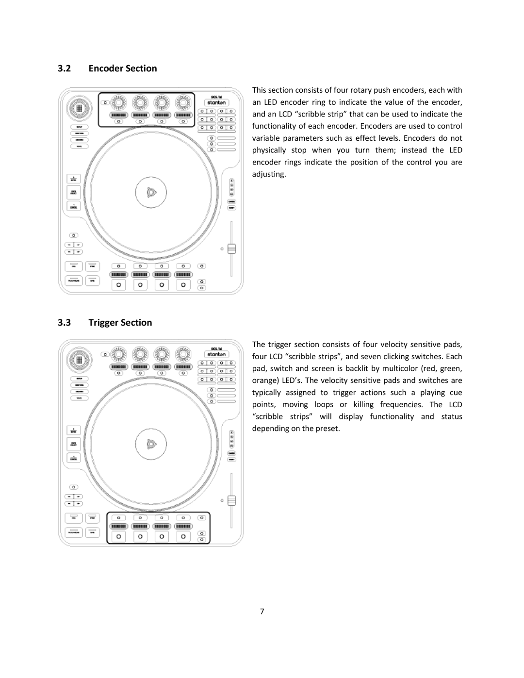
The Stanton SCS.1d is a pioneering piece of technology within the realm of digital DJing and music production. Designed with a focus on portability, functionality, and professional capabilities, it offers DJs and producers a versatile tool for both live performances and studio work.One of the standout features of the SCS.1d is its intuitive layout, which includes a range of control surfaces. The unit features a set of high-resolution touch-sensitive pads that can be used for triggering samples, loops, or one-shots with precision. This allows for an expressive performance style, letting DJs manipulate sounds in real-time to create unique mixes.
Another significant aspect of the SCS.1d is its integration of advanced control technologies such as MIDI and audio interfacing. It functions seamlessly with various DJ software, enabling users to customize their setups according to their preferences. The unit also supports multi-channel audio playback, allowing for complex mixing scenarios, which is essential for modern electronic music production.
The device is built with a robust casing designed to withstand the rigors of travel and frequent use, making it suitable for both club environments and home studios. The compact form factor ensures that it can easily fit into a DJ's gear bag alongside other equipment.
Additionally, the SCS.1d features customizable touch-sensitive sliders that provide an extra dimension of control. These sliders can be programmed for different functions, from adjusting volume levels to manipulating effects, offering users flexibility to configure their workspace according to the performance at hand.
Another key characteristic of the SCS.1d is its user-friendly interface, which is conducive to quick learning and mastery. The setup process is straightforward, allowing users to connect the device to their computer and be up and running in no time. This makes it an excellent choice for both novice and experienced DJs looking for an effective way to expand their sonic palette.
Overall, the Stanton SCS.1d stands out due to its high level of integration with software, robust design, and versatile control capabilities. It empowers music creators to explore new dimensions in their performances and productions, making it a valuable asset in a digital music toolkit.

