AC Voltage Coil Connection

Class H Coil (colored)

Class B Coil (black)


For

Power Line A

Power Line B

Tie Leads


Low voltage

1 and 3

2 and 4


High voltage

1

2

3 and 4


Figure 4

Table 1


Nominal

Maximum

% Torque

Required Torque

Original

Series

Static Torque

Counterclock-

Reduction

Adjust Screw

Spring Height


(lb-ft)

wise Turns

per Turn

Length (inches)

(inches)


55,500

1.5

4

12

2

1

55,300

3, 6 & 10

4

12

2

7/8

55,500

15

3

16

2-3/4

1-27/32

55,300


55,000

1.5

3

16

2

1-1/8

55,000


55,200

3, 6, 10 & 15

3

16

2

1

55,400


55,000


55,200

25

3

16

2-3/4

1-7/8

55,400


57,500


57,500

10

3

16

2

1

57,500

15

3

16

2

7/8

55,000


55,400

20

3

16

2-3/4

1-7/8

57,500


Figure 5

Figure 6


DC Voltage Coil Connection


Class H


Class B


Mechanical Switch (Old Style)

Electronic Switch** (New Style)

*Arc suppression used for coil above 48 Vdc. **Follow polarity for switch to operate.

Figure 7

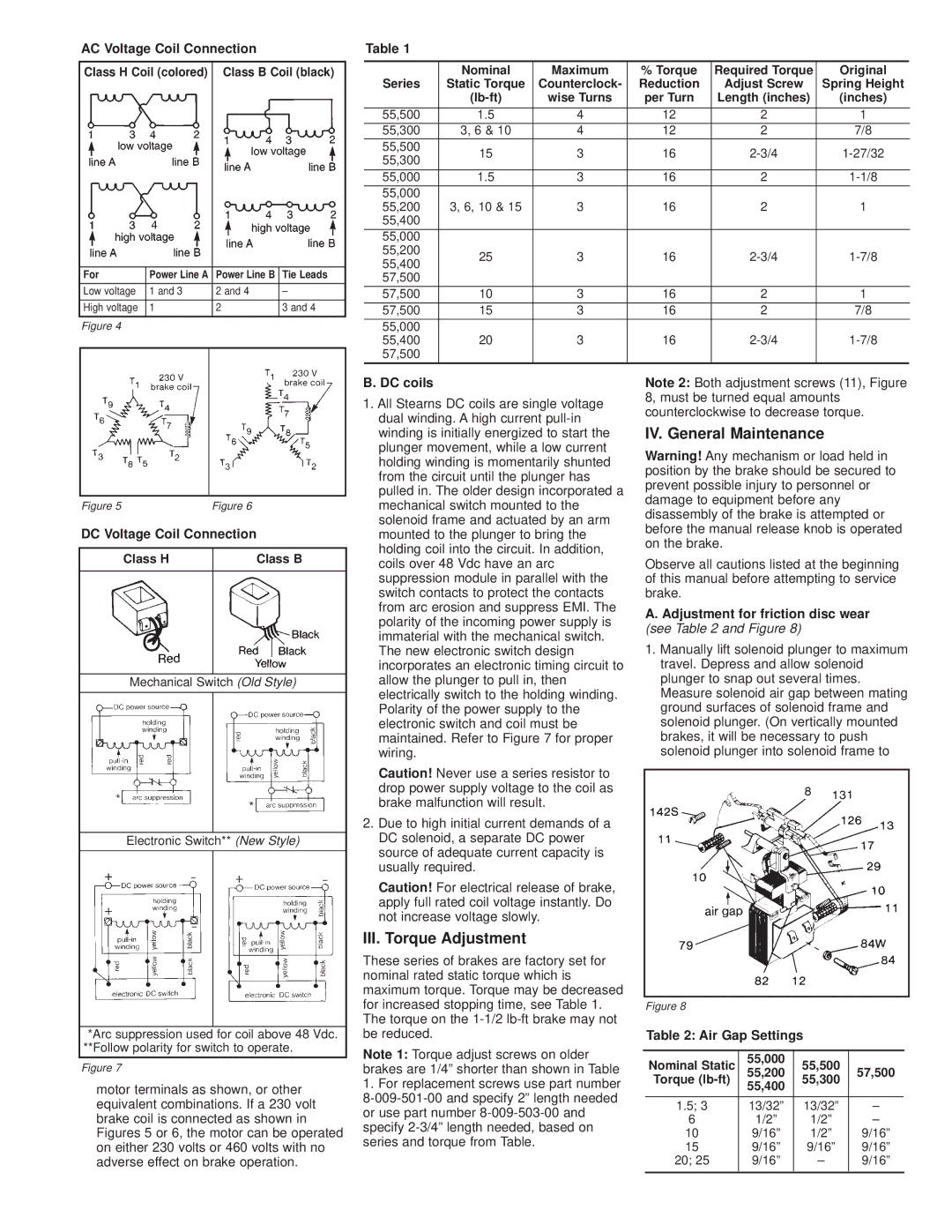
motor terminals as shown, or other equivalent combinations. If a 230 volt brake coil is connected as shown in Figures 5 or 6, the motor can be operated on either 230 volts or 460 volts with no adverse effect on brake operation.

B. DC coils

1.All Stearns DC coils are single voltage dual winding. A high current pull-in winding is initially energized to start the plunger movement, while a low current holding winding is momentarily shunted from the circuit until the plunger has pulled in. The older design incorporated a mechanical switch mounted to the solenoid frame and actuated by an arm mounted to the plunger to bring the holding coil into the circuit. In addition, coils over 48 Vdc have an arc suppression module in parallel with the switch contacts to protect the contacts from arc erosion and suppress EMI. The polarity of the incoming power supply is immaterial with the mechanical switch. The new electronic switch design incorporates an electronic timing circuit to allow the plunger to pull in, then electrically switch to the holding winding. Polarity of the power supply to the electronic switch and coil must be maintained. Refer to Figure 7 for proper wiring.

Caution! Never use a series resistor to drop power supply voltage to the coil as brake malfunction will result.

2.Due to high initial current demands of a DC solenoid, a separate DC power source of adequate current capacity is usually required.

Caution! For electrical release of brake, apply full rated coil voltage instantly. Do not increase voltage slowly.

III. Torque Adjustment

These series of brakes are factory set for nominal rated static torque which is maximum torque. Torque may be decreased for increased stopping time, see Table 1. The torque on the 1-1/2 lb-ft brake may not be reduced.

Note 1: Torque adjust screws on older brakes are 1/4” shorter than shown in Table

1.For replacement screws use part number 8-009-501-00 and specify 2” length needed or use part number 8-009-503-00 and specify 2-3/4” length needed, based on series and torque from Table.

Note 2: Both adjustment screws (11), Figure 8, must be turned equal amounts counterclockwise to decrease torque.

IV. General Maintenance

Warning! Any mechanism or load held in position by the brake should be secured to prevent possible injury to personnel or damage to equipment before any disassembly of the brake is attempted or before the manual release knob is operated on the brake.

Observe all cautions listed at the beginning of this manual before attempting to service brake.

A. Adjustment for friction disc wear (see Table 2 and Figure 8)

1.Manually lift solenoid plunger to maximum travel. Depress and allow solenoid plunger to snap out several times. Measure solenoid air gap between mating ground surfaces of solenoid frame and solenoid plunger. (On vertically mounted brakes, it will be necessary to push solenoid plunger into solenoid frame to

Figure 8

Table 2: Air Gap Settings


Nominal Static

55,000

55,500


55,200

57,500


Torque (lb-ft)

55,300


55,400


1.5; 3

13/32”

13/32”


6

1/2”

1/2”


10

9/16”

1/2”

9/16”


15

9/16”

9/16”

9/16”


20; 25

9/16”

9/16”


S-652-2

Page 3
Image 3
Stearns 300, 200, 55, 500 manual III. Torque Adjustment, IV. General Maintenance

500, 300, 0, 200, 55 specifications

The Stearns 55 is a remarkable piece of marine technology that stands out for its exceptional design and high-performance capabilities. Crafted for both leisure and commercial use, the vessel boasts a range of features and technologies that make it suitable for varied maritime activities.

One of the standout characteristics of the Stearns 55 is its impressive length of 55 feet, which provides ample space for passengers and cargo. The vessel is designed with a clean and modern aesthetic, complemented by a sleek hull that not only enhances its visual appeal but also its hydrodynamic efficiency. The design minimizes drag, allowing for faster speeds and improved fuel efficiency.

The Stearns 55 is equipped with advanced navigation technology, including a state-of-the-art GPS system that ensures precise positioning and safe navigation even in challenging conditions. Its radar system further enhances safety, allowing operators to detect obstacles and other vessels from a distance. Coupled with AIS (Automatic Identification System), the Stearns 55 enhances situational awareness, making it an ideal choice for busy waterways.

Moreover, the vessel can be powered by a variety of engine configurations, offering flexibility to its users. Whether opting for a diesel or hybrid engine, the Stearns 55 is designed to deliver robust performance with lower emissions, adhering to modern environmental standards. The engine room is designed for easy access, facilitating efficient maintenance and minimizing downtime.

Another noteworthy feature of the Stearns 55 is its spacious and comfortable interior. The layout is designed to optimize both functionality and comfort, accommodating up to six passengers. High-quality materials and finishes create a luxurious atmosphere, making long voyages enjoyable. The galley is equipped with modern appliances, and the open-plan salon provides ample seating and panoramic views of the surrounding waters.

Safety is paramount in the Stearns 55, with features such as a reinforced hull, multiple watertight compartments, and advanced firefighting systems. The vessel is fabricated using high-strength materials, ensuring durability and resilience against rough seas.

In summary, the Stearns 55 is a fusion of cutting-edge technology and elegant design, making it a versatile and dependable choice for both recreational and commercial maritime endeavors. Through its impressive array of features and a commitment to safety and performance, it stands out as a leading option in its class.