S |
|
|
|
|
|
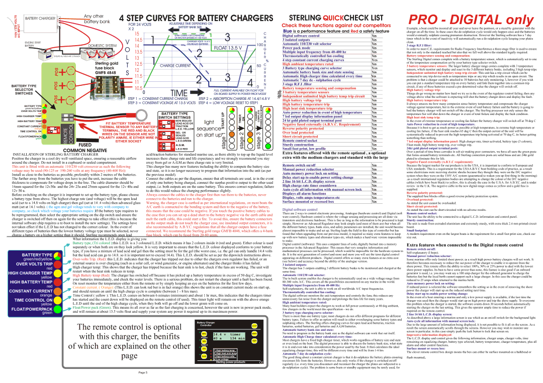
| Any other | 4 STEP CURVES FOR BATTERY CHARGERS | ||||||||||
T | BATTERY CHARGER | POS |
|
| ||||||||||||||
O |
|
|
| |||||||||||||||
L |
|
|
| battery bank |
|
|
|
|
|
|
|
|
|
|
| |||
V | T |
|
|
|
|
| FOR 24 VOLTS | ADJUSTABLE TIME DEPENDING ON |
|
|
|
|
| |||||
0 |
|
| NEG |
|
|
|
|
|
|
|
| |||||||
3 | U |
|
|
|
|
| X 2 |
|
|
| BATTERY BANK SIZE |
|
|
|
|
| ||
2 P |
|
|
|
|
|
|
|
|
|
|
|
|
| |||||
/ | N |
|
|
|
|
|
|
|
|
|
|
|
| 3 |
|
|
| |
V | I |
|
|
|
|
|
|
| 15 |
|
|
|
|
|
|
| C | |
C |
|
|
|
|
|
|
|
|
|
|
|
|
|
| ||||
0 |
|
|
|
|
|
|
| 1 |
| EXTRA CHARGE FOR COVENTIONAL |
|
|
| |||||
1 | / |
|
|
|
|
|
|
|
|
|
|
|
| |||||
1 | A |
|
|
|
|
|
| V | 14.5 |
| OR TRACTION BATTERIES AT 14.8 VOLTS |
|
|
| H | |||
|
|
|
|
|
|
|
|
|
|
|
| |||||||
| ENGINE START |
|
|
|
|
|
|
| CHARGER VOLTS 14.4 V |
|
|
| A | |||||
| BATTERY |
|
|
|
|
| DOMESTIC SYSTEM | 14 |
| GEL/SEALED BATTERIES | FLOAT 13.5 V | 100 R | ||||||
|
|
|
|
|
|
|
| O 13.5 |
|
|
| 2 |
| G | ||||
|
|
|
|
|
|
|
|
|
|
|
|
|
|
| E | |||
|
|
| ENSURE ALL NEGS ARE COMMON |
| L | 13 | 1 CHARGE CURRENT |
|
|
|
| R | ||||||
|
|
|
|
|
|
| Sterling gold | T | 12.5 |
|
|
| 4 |
| % | |||
|
|
|
|
|
|
|
|
|
| 50 | C | |||||||
|
|
| POS |
|
| fuse block |
|
|
| |||||||||
|
|
|
|
| S | 11.5 |
|
|
|
|
|
|
| U | ||||
|
|
|
|
| GMFB 4848 |
|
|
|
|
|
|
| R | |||||
|
|
|
|
|
|
|
| 12 |
|
|
| 2 |
| 3 |
| R | ||
|
|
| POS |
|
|
|
|
| 11 |
|
|
|
| 4 |
| E | ||
BATTERY TYPE |
|
|
|
|
|
|
|
|
|
|
| 0 | N | |||||
SELECTOR |
|
|
|
|
|
| 10.5 |
| TIME |
| FULL CURRENT AVAILABLE ON FLOAT FOR | T | ||||||
SWITCHES |
| POS |
|
|
|
|
|
|
|
| ON BOARD SUPPLY IN POWER PACK MODE | |||||||
|
|
|
|
|
|
|
|
|
|
|
|
| ||||||
|
|
|
|
|
|
| STEP 1 = CONSTANT CURRENT CHARGE | STEP 2 = ABSORPTION CHARGE AT 14.4/14.8 V | ||||||||||
|
|
|
|
|
|
|
| |||||||||||
|
|
|
|
|
|
|
| STEP 3 = CONSTANT VOLTAGE AT 13.5 VOLTS | STEP 4 = LOW VOLTAGE RESET TO STEP1 |
| ||||||||
| BATTERY TYPE |
|
|
|
|
|
|
|
|
|
|
|
|
|
|
| 3stageCOMPLETECHARGE PACKPOWERMODE |
|
| green/red/yellow | 12 |
| ON | REMOTE CONTROL | FUSED |
|
| 121212 | ONON |
|
|
| 1stageUPSTART | 2stage |
| ||
| OVER VOLTS TRIP |
|
|
|
|
|
|
| ||||||||||
| red |
|
|
|
|
|
|
|
|
| BATTERY TYPE |
|
|
| TIMER ON |
|
| |
HIGH CHARGER TEMP |
|
|
|
|
|
|
|
| SWITCH SETTINGS |
|
|
|
|
| ||||
| yellow |
|
|
|
|
|
|
|
| light |
|
|
|
| ||||
| HIGH BATTERY TEMP |
|
|
|
|
| FIT BATTERY TEMPERATURE | ON | NON SEALED |
|
|
|
| |||||
| red |
|
|
|
|
| LEAD ACID OR |
|
|
|
| |||||||
| CONSTANT CURRENT |
|
|
|
|
| THERMAL SENSOR TO ANY BATTERY | TRACTION | sequence |
|
|
| ||||||
| orange |
|
|
|
|
|
| L.E.D. YELLOW |
|
|
|
| ||||||
|
|
|
|
|
| TERMINAL, THE RED AND BLACK |
|
|
|
|
|
|
|
| ||||
| TIME CONTROL ON |
|
|
|
|
|
| GEL OR | on start up |
|
|
|
| |||||
| yellow |
|
|
|
|
| WIRES ON THE SENSOR ARE NOT |
|
|
|
|
| ||||||
| FLOAT/POWERPACK |
|
|
|
|
|
| SEALED |
|
|
|
| ||||||
| green |
|
|
|
|
| POLARITY AWARE, IE EITHER WIRE IN |
| LEAD ACID |
|
|
|
|
|
| |||
|
|
|
|
|
|
| EITHER SOCKET |
|
| L.E.D.GREEN |
|
|
|
|
|
| ||
|
|
|
|
|
|
|
|
|
|
|
| A.G.M. |
|
|
|
|
|
|
|
|
|
|
| COMMON NEGATIVE |
|
|
|
| L.E.D RED |
|
|
|
|
|
| ||
|
|
|
|
|
|
| acid/traction batteries for standard marine use, as there ability to top up the liquid level | |||||||||||
INSTALLATION OF STERLING BATTERY CHARGER |
|
| ||||||||||||||||
Position the charger in a cool dry well ventilated space, ensuring a reasonable airflow | increases there charge rate and life expectancy and we strongly recommend you stay | |||||||||||||||||
around the charger. Do not install in a cupboard or sealed compartment. |
|
| away from gel or A.G.M.as there charge rate is very limited. |
|
|
| ||||||||||||
This unit is fitted with an automatic 110/230 volt crossover as such the following |
| This charger has many new features including the ability to compute the battery size | ||||||||||||||||
voltage may be used |
|
| and state, so it is no longer necessary to program that information into the unit (as per | |||||||||||||||
Install as close to the batteries as possible, preferably within 2 metres of the batteries. | the previous model). |
|
|
|
|
|
| |||||||||||
The further away from the batteries you have to put the unit, increase the cable |
| Connect the cables as per the diagram, ensure that all terminals are used, ie in the event | ||||||||||||||||
thickness to compensate for voltage drops in the line. The cable diameter should be |
| of only one battery being charged, connect the surplus positive output to the other used | ||||||||||||||||
16mm squared for the 12v30a and the 24v 25a and 25mm squared for the 12v 40a and | output, i.e. both outputs are on the same battery. This ensures correct regulation; failure | |||||||||||||||||
12v 50 a. |
|
|
|
|
|
|
|
| to do this would reduce the charging performance slightly. |
|
|
| ||||||
Before switching on the charger it is important to set up the battery type, please choose | Always connect the cables to the charger first then run them to the batteries, never | |||||||||||||||||
a battery type from above. The highest charge rate (and voltage) will be the open lead | connect to the batteries and run to the charger. |
|
|
|
|
| ||||||||||||
acid (set to a 14.8 volts on high charger) then gel (set at 14 .4 volts) then advanced glass | Warning, the charger case is earthed as per international regulations, on most boats the | |||||||||||||||||
matt (set at 14.1 volts). ( the agm and gel voltage tends to vary with company to |
| A/C earth is connected to the bonding system and then to the negative of the battery, | ||||||||||||||||
company, so check which voltage your batteries require )If the battery type requires to | this means that the case could be negative. If you touch the positive battery cables to | |||||||||||||||||
be reprogrammed, then select the appropriate setting on the dip switch and ensure the | the case then you can set up a dead short to the battery negative via the earth cable and | |||||||||||||||||
charger is switched off then on again for the settings to take effect (this is because the | melt the earth cable, this could start a fire. To avoid this, ensure the battery connectors | |||||||||||||||||
internal software chip requires a | on the output studs do not touch the charger case, use insulated output connectors, it is | |||||||||||||||||
not taken effect if the L.E.D has not changed to the correct colour. In the event of |
| also recommended by A.B.Y.C. regulations that all the charger outputs have a fuse | ||||||||||||||||
different types of batteries then the lowest battery voltage type must be selected, never | connected. We recommend the Sterling gold range GMFB 4848, which offers a | |||||||||||||||||
charge a battery on a higher setting than it should, Sterling recommends open lead |
| fuse block, which can be fused from |
|
|
|
| ||||||||||||
|
|
|
|
|
| What information the L.E.D. display is giving you |
|
|
|
|
|
|
|
| ||||
|
|
|
|
|
| Battery type, (Tri colored ):this L.E.D. is a 3 coloured L.E.D. which means it has 2 colours inside it (red and green). Either colour is used | ||||||||||||
separately or when both are on they look yellow. It is very important to ensure that the L.E.D. colour displayed conforms to your battery type, if you have a mixture of lead acid and gel then the setting must be for the gel (the worst case, i.e. the gel can only handle 14.4 volts but the lead acid can go to 14.8. so it is important not to exceed 14.4). This L.E.D. should be set as per the dipswitch instructions above.
![]()
![]() external source is over charging (such as a solar cell, or wind generator, or engine alternator) and the charger thinks it has failed.
external source is over charging (such as a solar cell, or wind generator, or engine alternator) and the charger thinks it has failed.
High charger temp: This shows that the charger has tripped because the heat sink is to hot, check if the fans are working. The unit will restart when the heat sink reduces in temp.
High Battery temp (Red): The charger has switched off because it has picked up a battery temperature in excess of 50 deg C, investigate your batteries immediately, and check the water levels. There is a serious problem, do not restart the charger until a fault has been found.
On reset monitor the temperature either from the remote or by simply keeping an eye on the batteries for the first few days.
Constant current. ( Orange): (This L.E.D. can look red but is in fact orange) this shows the unit is on constant current mode on start up, and should remain on until the high charge cycle is complete (between 1 - 8 hrs max).
Time Control ( yellow ): This L.E.D. comes on between 6 minutes (minimum) and about 1 hr max, this indicates that the chargers timer has started and the count down will be displayed on the remote control (if used). This timer light will remain on with the above orange
L.E.D until the end of the high charge cycle, when they both will go off and the lower green will come on.
![]() Float/Power pack (Green). This means its all over as far as the fast charging is concerned, however the unit is now in power pack mode, and will remain at about 13.5 volts float and supply your system any power it required up to its maximum power.
Float/Power pack (Green). This means its all over as far as the fast charging is concerned, however the unit is now in power pack mode, and will remain at about 13.5 volts float and supply your system any power it required up to its maximum power.
STERLING QUICKCHECK LIST
Check these functions against out competitors
Blue is a performance feature and Red a safety feature
|
|
|
| Digital software control | Yes |
|
|
|
|
| 3 isolated outputs | Yes |
|
|
|
|
| Automatic 110/230 volt selector | Yes |
|
|
|
|
| Power pack mode | Yes |
|
|
|
|
| Multiple input frequency from | Yes |
|
|
|
|
| Thermostatically controlled fan cooling | Yes |
|
|
|
|
| 4 step constant current charging curves | Yes |
|
|
|
|
| High ambient temperature rated | Yes |
|
|
|
|
| 3 Battery type charging curve selector | Yes |
|
|
|
|
| Automatic battery bank size and state sensing | Yes |
|
|
|
|
| Automatic High charger time calculated every time | Yes |
|
|
|
|
| Automatic 7 day de - sulphation cycle | Yes |
|
|
|
|
| 3 stage R.F.I .filter | Yes |
|
# |
|
| Battery temperature sensing and compensation | Yes |
| |
|
| 3 battery temperature sensors | Yes |
| ||
# | Independent unlimited high battery temp trip circuit | Yes |
| |||
|
|
|
| High battery voltage trip | Yes |
|
|
|
|
| High battery temperature trip | Yes |
|
|
|
|
| High heat sink temperature trip | Yes |
|
|
|
|
| Auto power reduction in event of high temperature | Yes |
|
|
|
|
| 7 led output display information panel | Yes |
|
|
|
|
| 24 kt gold plated output terminal post | Yes |
|
|
|
|
| Negative fused externally (A.B.Y.C. Requirement) | Yes |
|
|
|
|
| Reverse polarity protected | Yes |
|
|
|
|
| Over load protected | Yes |
|
|
|
|
| Short circuit protected | Yes |
|
|
|
|
| Remote control socket | Yes |
|
|
|
|
| Sturdy construction | Yes |
|
|
|
|
| Small foot print, low profile | Yes |
|
Extra features offered with the remote optional , a optional
extra with the medium chargers and standard with the large
| Remote switch on/off | Yes | |
| Manual power reduction selector | Yes | |
| Auto memory power lock on setting | Yes | |
| Delay start up to enable power setting change | Yes | |
| 2 line 16 bit L.C.D. display screen | Yes | |
| High charge rate timer countdown | Yes |
|
| Auto cycle all information with manual screen lock | Yes | |
| Displays all alarm functions | Yes | |
| Display, volts amps temperatures etc | Yes | |
| Surface mounted or recessed box | Yes | |
Digital software control
There are 2 ways to control electronic processing, Analogue (hardware control) and Digital (soft ware control). Hardware control is where the voltage sensing and processing are all done via transistors and electronic hardware. This is fine as long as the information to be processed is kept simple. However an Advanced Regulator may look simple (and most of them are) but when all the different battery types, bank sizes, and safety parameters are installed, the unit would become almost impossible to make and set up. Sterling leads the field in this type of controller but has found that when upgrading from our previous model, it required so many extra features to keep up with new battery types and alternator types etc, which makes a hard ware version impossible to make.
Digital control (software): This uses computer lines of code, digitally burned into a memory processor in the Advanced Regulator. This means that very complex information and mathematical processes can be processed, which would be impossible for the hardware system to do. It is the next generation of control and more and more you will see the term digital control appearing on different products. Digital control offers so many extra features at no extra cost (see below) and accuracy beyond the ability of the analogue version.
3 isolated outputs:
The charger has 3 outputs enabling 3 different battery banks to be monitored and charged at the same time.
Automatic 110/230 volt selector:
The in built system enables the charger to be automatically used on a wide voltage range from
Multiple input frequencies from
Thermostatically controlled fan cooling:
The digital software monitors the unit temperature and controls the fans; this reduces any unnecessary fan noise from the charger and prolongs the fans life for many years.
High ambient temperature rated:
Many boat builders expect the chargers to work at full power continuously at 40 deg ambient, few chargers in the world meet this specification - we do.
3 battery type charging curve selector:
PRO - DIGITAL only
Example, a boat could be moored all year and never leave the pontoon, or a stand by generator with the charger on all the time. In these cases the
3 stage R.F.I filter:
In order to meet C.E. requirements for Radio Frequency Interference a
Battery temperature sensing and compensation:
The Sterling Digital comes complete with a battery temperature sensor, which is automatically set to one of the temperature compensation set by your battery type selector switch.
3 battery temperature sensors: The larger battery charger range comes complete with 3 temperature sensors, which monitor and display and react to the 3 different battery banks, including 3 high temp trips Independent unlimited high battery temp trip circuit: This unit has a trip circuit which can be connected to any trip device such as temperature trips or any trip which results in an open circuit. The problem is that a charger could be attached to 10 batteries but only monitoring 3, however if you wish you can put a standard temperature trip on every battery and link them together into a common trip circuit, if any of these batteries exceed a pre determined value the charger will switch off.
High battery voltage trip:
Things do go wrong no matter how hard we try so in the event of the regulator control failing, then any voltage above what the software is expecting will shut the battery charger down and display the fault.
High battery temperature trip:
It always amazes me how many companies sense battery temperature and compensate the charger voltage against temperature, but in the extreme event of total battery failure and the battery is going to boil the battery charger will not switch off the charger. The Sterling processor not only senses the temperature but will shut down the charger in event of total failure and display the fault condition.
High heat sink temp trip:
In the event of extreme temperature or cooling fan failure the battery charger will switch off at 70 deg C
Auto Power reduction in event of high temperature.
Because it is best to get as much power as possible at high temperature, in extreme high temperature or cooling fan failure, if the heat sink reaches 65 deg C then the output current of the unit will be systematically reduced to prevent the high temperature trip being activated at 70 deg C, its better getting something than nothing.
7 led output display information panel: High charger rate, timer activated, battery type (3 colours), Float mode, high battery temp trip, over voltage trip,
24kt gold plated output terminal posts:
Over a period of time brass corrodes in salt air making poor connectors, we have all seen the green paste that forms around battery terminals etc. All Sterling connection posts are solid brass and are 24kt gold plated to eliminate this for life.
Negative Fused externally (A.B.Y.C requirement):
Because the largest market for our products is in the USA, it is important to conform to European and USA standards. This is a requirement for the USAA.B.Y.C boat building code of practice, as a result some electricians were receiving electric shocks because they thought they were on the D/C negative system when they were on the 110V A/C system (guaranteed to waken you up first thing in the morning)
.as a result international regulation bodies are attempting to change the colour of the D/C negative cables (which have been black) to yellow, this is already the case in the U.S.A. for A.B.Y.C. and is under review in the U.K. The negative cable in the new digital range comes as yellow and a gold fuse is supplied.
Reverse polarity protected:
The supplied fuse blocks offers a good reverse polarity protection system.
Overload protected:
As stated the unit cannot be overloaded.
Short circuit protected:
As stated the cant can be
Remote control socket:
The unit has the ability to be connected to a digital L.C.D. information and control panel.
Sturdy construction:
The unit is made from extruded aluminium and extremely sturdy, with extra thick 2.4 mm printed circuit board.
Small footprint:
A modern requirement even on the largest boats is the requirement for a small foot print size, check our size out.
Extra features when connected to the Digital remote control
Remote switch on/off:
Manual power reduction selector:
Some marinas offer only limited shore power; as a result high power battery chargers will not work. It therefore becomes necessary to reduce the out power of the charger to enable it to operate from the shore power. This remote offers the ability to select 100%, 50% or 25% power to deal with the lowest shore power supplies. Its best to have some power than none, this feature is also good if an onboard generator is used, i.e. you may want say a 100 amp charger for the onboard generator to charge the batteries fast but the local berth cannot support such a large charger. In this case the charger could be reduced to 25 amps when returned to the marina berth.
Auto memory power lock on setting:
If reduced power is selected the software remembers the setting so in the event of removing the shore power the charger will start up on the reduced setting next time.
Delay start up to enable power setting change:
In the event of a boat entering a marina and only a low power supply is available, if the last time the charger was used then the charger would start up on high power and trip the shore supply. To overcome this problem when the charger is started, the software counts down 30 seconds before automatically starting the charger on the last setting. This gives the operator ample time to reduce the power if required on the remote control.
2 line 16 bit L.C.D. display screen:
The remote control is optional with this charger, the benifits
of which are explained on the other
page
Battery Charger |
|
Controller | on/off |
100% | 14.4 v | timer | alarm | |
40 a | 134 min | |||
Power |
| |||
50% | light | |||
|
| |||
|
|
| ||
Select |
|
|
| |
25% | 1 High battery temp |
| ||
|
| |||
| 2 High heat sink temp |
| ||
hold | 3 High battery volts |
| ||
| 4 Low voltage |
| CE | |
| Sterling power products | |||
There is more than one battery type; most chargers do not offer different programs for different battery types. Failure to offer an option will result in either overcharging some battery types and sulphating others. The Sterling offers charging curves for open lead acid batteries, traction batteries, sealed batteries, gel batteries and A.G.M batteries.
Automatic battery bank size and state:
No need to program in the battery bank size as the digital software can work that out itself.
Automatic High Charge timer calculated every time:
Most chargers have a fixed high charger timer, which works regardless of battery size and state or even load on the boat. The digital processor is able to discern the battery bank size, what state it is in and even take into consideration the power used by the boat. It then calculates the ideal equalizing charger time; this will be different every time and will be from
Automatic 7 day de-sulphation cycle:
The good thing about a constant current charger is that it
As described above a large information screen is use which as an on/off switch for the background light.
Auto cycle all information with manual screen lock:
Due to the large amount of information being displayed, it is not possible to fit it all on the screen. As a result the screen automatically scrolls through the screens. However you may wish to monitor one screen in particular, in this case simply push the lock button to lock that screen on.
Impressive information displayed:
The L.C.D. display and control gives the following information, charger amps, charger volts, time remaining on equalizing charger, battery type selected, battery temperature, charger temperature, plus all alarm and other control functions.
Surface mount or recess box:
The clever remote control box design means the box can either be surface mounted on a bulkhead or
flush mounted.
Page 5