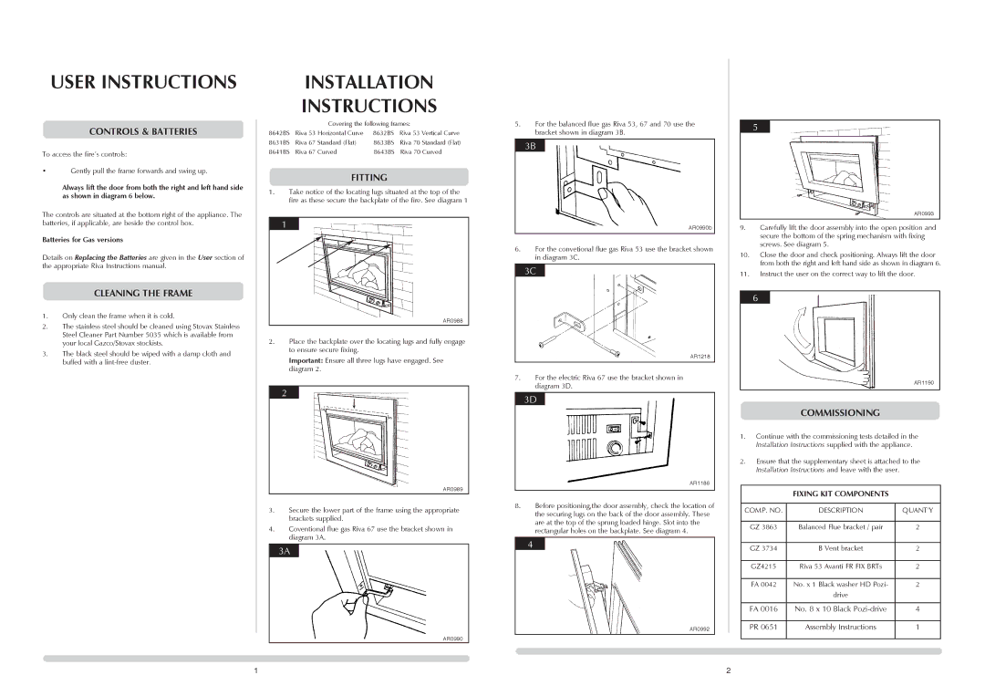
PR0651 specifications
The Stovax PR0651 is an exceptional multi-fuel stove that embodies both traditional craftsmanship and modern innovation, making it a standout choice for homeowners seeking a reliable and efficient heating solution. This stove is designed to accommodate a variety of solid fuels, including wood, coal, and peat, offering great flexibility, especially in areas where fuel availability may vary.One of the main features of the Stovax PR0651 is its efficient heating capability. With a nominal output of 5 kW, it is designed to warm medium-sized rooms effectively, delivering a cozy ambiance without overpowering the space. The stove boasts an impressive efficiency rating of over 80%, ensuring that a significant portion of the energy from the fuel is converted into usable heat. This efficiency not only reduces fuel consumption but also minimizes emissions, making it an environmentally friendly option.
The PR0651 incorporates advanced air wash technology, which helps to keep the glass door clean and clear. This feature enhances the viewing experience by providing a stunning view of the flames while also reducing the need for frequent cleaning. The stove's combustion system is designed to optimize airflow, promoting complete combustion of the fuel and ensuring minimal smoke and particulate matter are released into the atmosphere.
The design of the Stovax PR0651 is another highlight, blending contemporary aesthetics with a classic stove appearance. The clean lines and sleek finish make it a stylish addition to any home decor. It is available in a range of finishes, including black, enamel, and stainless steel, allowing homeowners to choose a look that complements their interior design.
Another characteristic worth noting is the stove’s robust construction, which ensures durability and longevity. Made from high-quality cast iron and steel, the PR0651 is built to withstand the rigors of regular use. The stove is designed with a large door opening for easy fueling and maintenance, while the built-in log storage compartment offers convenient storage for fuel.
In terms of installation, the Stovax PR0651 is flexible, compatible with both traditional flue systems and modern balanced flue installations, making it suitable for various homes and conditions. With its combination of efficiency, style, and advanced technology, the Stovax PR0651 stands out as a top choice for homeowners looking to enhance their interior spaces while ensuring a warm and inviting atmosphere.

