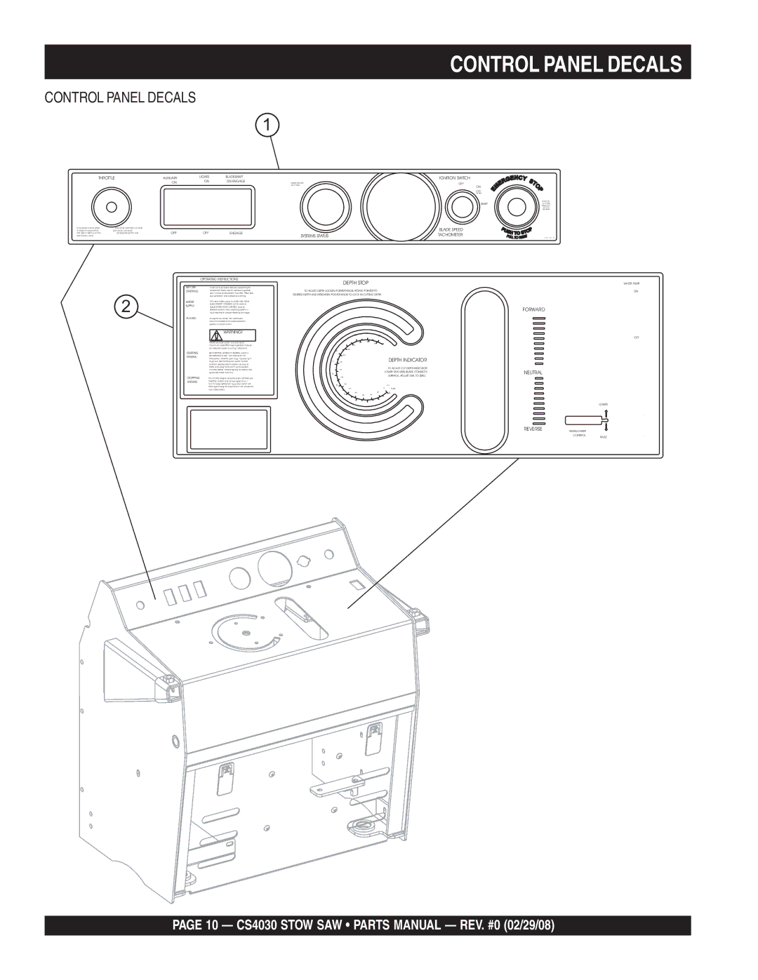
CONTROL PANEL DECALS
CONTROL PANEL DECALS
1
THROTTLE | AUXILIARY | LIGHTS | BLADESHAFT | ||
| ON |
| |||
|
| ON |
| ||
TO INCREASE ENGINE SPEED: | TURN KNOB COUNTERCLOCKWISE . |
|
|
|
|
TO REDUCE ENGINE SPEED: | TURN KNOB CLOCKWISE. |
|
|
|
|
FOR QUICK THROTTLE ACTION: | DEPRESS RED BUTTON AND | OFF |
| OFF | ENGAGE |
PUSH OR PULL KNOB. |
|
|
|
|
|
|
|
|
| OPERATING INSTRUCTIONS | |
|
|
| BEFORE |
| Check all fluid levels. Secure blade firmly to |
|
|
| STARTING: |
| bladeshaft. Make sure all protective guards |
|
|
|
|
| are in place and properly mounted. Wear eye, |
| 2 |
|
|
| ear protection and protective clothing. |
|
| WATER |
| Connect water supply to water inlet. Move | |
|
|
| SUPPLY: |
| water ON/OFF CONTROL to ON position. |
|
|
|
| Adjust WATER FLOW CONTROL lever to | |
|
|
|
|
| desired position. Drain watering system in |
|
|
|
|
| cold weather to prevent freezing damage. |
|
|
| BLADES: |
| Always follow blade manufacturer's |
|
|
|
|
| recommendations for blade selection, |
|
|
|
|
| speed and application. |
|
|
|
|
| WARNING! |
|
|
|
|
| NEVER exceed blade manufacturer's |
|
|
|
|
| maximum rated RPM. See operator's manual |
|
|
|
|
| for detailed blade mounting instructions. |
|
|
| STARTING |
| Set CONTROL HANDLE to NEUTRAL position. |
|
|
| ENGINE: |
| Set THROTTLE to IDLE. Turn start switch to |
|
|
|
|
| ON position. Wait for glow plug indicator light |
|
|
|
|
| to go out. Momentarily turn switch to start |
|
|
|
|
| position; release switch as soon as engine |
|
|
|
|
| starts. Allow engine to warm up for several |
|
|
|
|
| minutes before increasing engine speed. Use |
|
|
|
|
| approved diesel fuel only. |
|
|
| STOPPING | Do not stop engine abruptly when hot! Reduce | |
|
|
| ENGINE: | THROTTLE to IDLE and allow engine to run 1 | |
to 2 minutes before turning ignition switch off. Damage to engine may occur if not allowed to cool adequately.
| IGNITION SWITCH |
ENGINE | OFF |
GLOW PLUG | |
| ON |
| ENGINE |
|
| ENGINE WILL |
START | NOT CRANK |
WHEN | |
| BUTTON IS |
| DEPRESSED |
| BLADE SPEED |
SYSTEMS STATUS | TACHOMETER |
37731 REV 04 |
| DEPTH STOP |
|
| WATER PUMP | ||
TO ADJUST DEPTH LOOSEN POINTER KNOB, ROTATE POINTER TO |
| ON | ||||
DESIRED DEPTH AND RETIGHTEN POINTER KNOB TO LOCK IN CUTTING DEPTH. |
|
| ||||
|
|
|
|
|
| FORWARD |
|
| 10 | 11 |
|
|
|
|
|
| 12 |
| OFF | |
|
|
|
|
|
| |
| 9 | 260 | 280 |
|
|
|
|
|
| 300 |
|
| |
|
| 240 |
|
|
|
|
8 |
| 220 |
|
|
|
|
|
|
|
|
|
| |
| 200 |
|
|
|
|
|
7 180 |
|
|
| DEPTH INDICATOR |
| |
6 | 160 |
|
|
| TO ADJUST CUT DEPTH INDICATOR | NEUTRAL |
|
|
| LOWER SAW UNTIL BLADE CONTACTS | |||
| 140 |
|
|
| SURFACE, ADJUST DIAL TO ZERO. |
|
5 | 120 |
|
|
| mm |
|
|
|
|
|
| ||
|
| 100 |
| 0 | Inch |
|
|
| 80 |
| 20 | 0 |
|
| 4 |
| 40 |
| ||
|
| 60 |
|
| ||
31
2
REVERSE
LOWER
RAISE/LOWER
CONTROL
RAISE
PAGE 10 — CS4030 STOW SAW • PARTS MANUAL — REV. #0 (02/29/08)
