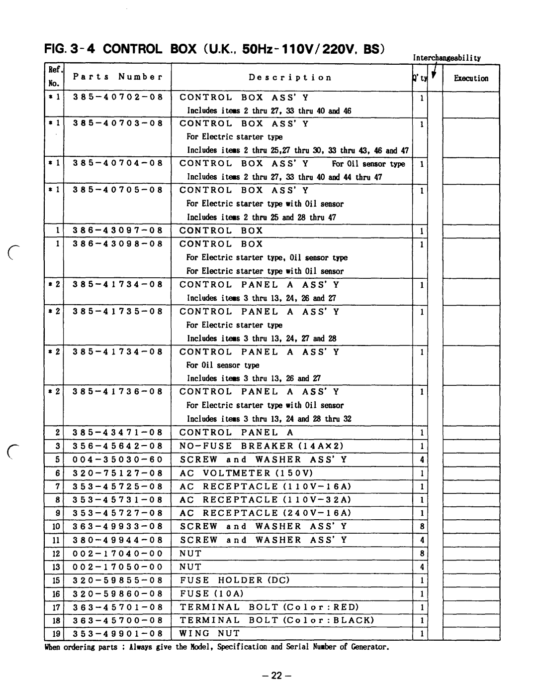
FIG. 3-4 CONTROL BOX (U.K., 50Hz- llOV/22OV, BS)
Inter&
seability
Ref
Parts Number
No.
*l
-
*I
*l
-
*l
-
*2
-
*2
-
22
*2
2
3
5
6
7
8
9
iii
11
12
15
17
Is
A
#en ordering parts ; Always give
|
|
|
| Description |
|
|
| |
CONTROL |
|
| BOX | ASS’ | Y |
|
| |
Includes itews 2 thru 27. 33 thru 40 and 46 |
| |||||||
CONTROL |
|
| BOX | ASS’ | Y |
|
| |
For Electric | starter | type |
|
|
| |||
Includes | itews | 2 thru | 25,2’7 thru 30, | 33 thru | 43, 46 and 47 | |||
CONTROL |
|
| BOX | ASS’ | Y | For Oil | sensor type | |
Includes itews 2 thru 27, 33 thru 40 and 44 thru 47 | ||||||||
CONTROL |
|
| BOX | ASS’ | Y |
|
| |
For Electric starter type with Oil sensor |
| |||||||
Includes itews 2 thru 25 and 2% thru 47 |
| |||||||
CONTROL |
|
| BOX |
|
|
|
| |
CONTROL |
|
| BOX |
|
|
|
| |
For Electric starter type, Oil sensor type |
| |||||||
For Electric starter type with Oil sensor |
| |||||||
CONTROL |
|
| PANEL | A | ASS’ | Y |
| |
Includes | itews | 3 thru | 13, 24, | 26 and 27 |
| |||
CONTROL |
|
| PANEL | A | ASS’ | Y |
| |
For | Electric | starter | type |
|
|
| ||
Includes | itews | 3 thru | 13, 24, | 27 and 28 |
| |||
CONTROL |
|
| PANEL | A | ASS’ | Y |
| |
For Oil | sensor | type |
|
|
|
| ||
Includes itews 3 thru 13, 26 and 27 |
|
| ||||||
CONTROL |
|
| PANEL | A | ASS’ | Y |
| |
For Electric starter type with Oil sensor |
| |||||||
Includes itees 3 thru 13, 24 and 28 thru 32 |
| |||||||
CONTROL |
|
| PANEL | A |
|
|
| |
|
| BREAKER | (14AX21 |
|
| |||
SCREW | and | WASHER | ASS’ | Y |
| |||
AC | VOLTMETER | (15OVl |
|
| ||||
AC | RECEPTACLE | (11 |
| |||||
AC | RECEPTACLE | (11 |
| |||||
NUT |
|
|
|
FUSE |
| HOLDER | (DC) |
FUSE | (1 OA) |
| |
TERMINAL | BOLT (Co 1 or : RED) | ||
TERMINAL | BOLT(Color:BLACK) | ||
WING |
| NUT |
|
the kdel, | Specification | and Serial Numberof Generator. | |
II
1
1
1
I11
1
1
I11 I 11
I 41
I 11
I11 I 11
4’
1
1
1
1 11
Execution
- 22 -
