6
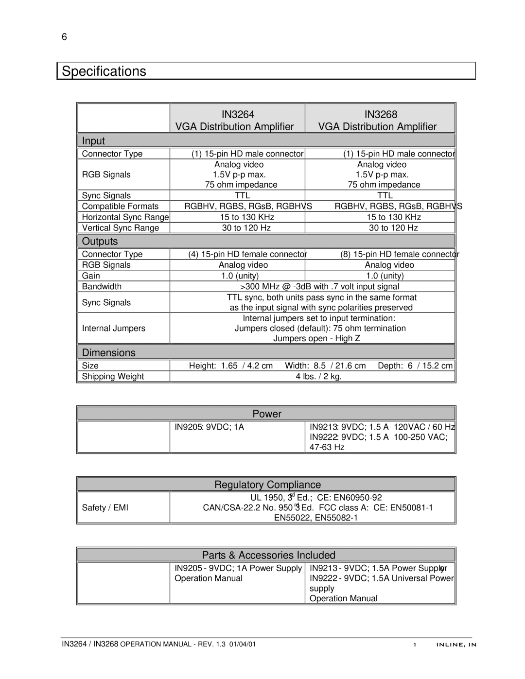
Specifications

 Input
Input
Connector Type
RGB Signals
Sync Signals
Compatible Formats
Horizontal Sync Range
Vertical Sync Range
IN3264
VGA Distribution Amplifier
(1)
Analog video 1.5V
75 ohm impedance
TTL
RGBHV, RGBS, RGsB, RGBHVS
15 to 130 KHz
30 to 120 Hz
IN3268
VGA Distribution Amplifier
(1)
Analog video 1.5V
75 ohm impedance
TTL
RGBHV, RGBS, RGsB, RGBHVS
15 to 130 KHz
30 to 120 Hz
![]()
![]() Outputs
Outputs
Connector Type
RGB Signals
Gain
Bandwidth
Sync Signals
Internal Jumpers

 Dimensions
Size
Shipping Weight
| (4) |
| (8) |
| Analog video |
| Analog video |
| 1.0 (unity) |
| 1.0 (unity) |
>300 MHz @
TTL sync, both units pass sync in the same format as the input signal with sync polarities preserved
Internal jumpers set to input termination:
Jumpers closed (default): 75 ohm termination
Jumpers open - High Z
Height: 1.65” / 4.2 cm Width: 8.5” / 21.6 cm Depth: 6” / 15.2 cm
4 lbs. / 2 kg.
Power
IN9205: 9VDC; 1A
IN9213: 9VDC; 1.5 A 120VAC / 60 Hz
IN9222: 9VDC; 1.5 A
Regulatory Compliance
Safety / EMI
UL 1950, 3rd Ed.; CE:
EN55022,
Parts & Accessories Included
IN9205 - 9VDC; 1A Power Supply Operation Manual
IN9213 - 9VDC; 1.5A Power Supply or IN9222 - 9VDC; 1.5A Universal Power supply
Operation Manual
IN3264 / IN3268 OPERATION MANUAL - REV. 1.3 01/04/01 | ©1999 INLINE, INC. |