
WA-7500M specifications
The Sunpentown International WA-7500M is an innovative evaporative air cooler designed to enhance indoor air comfort during hot weather. Featuring a compact design, it efficiently cools spaces while remaining energy-efficient, making it an ideal choice for those looking to maintain a comfortable environment without incurring high electricity bills.One of the standout features of the WA-7500M is its advanced evaporative technology, which works by absorbing heat from the air and replacing it with cool, refreshing airflow. This process not only lowers the temperature in your room but also adds moisture to the air, benefiting individuals who suffer from dry skin or respiratory issues. With a powerful motor, the cooler can effectively circulate air across larger areas, ensuring that your entire living space remains comfortable.
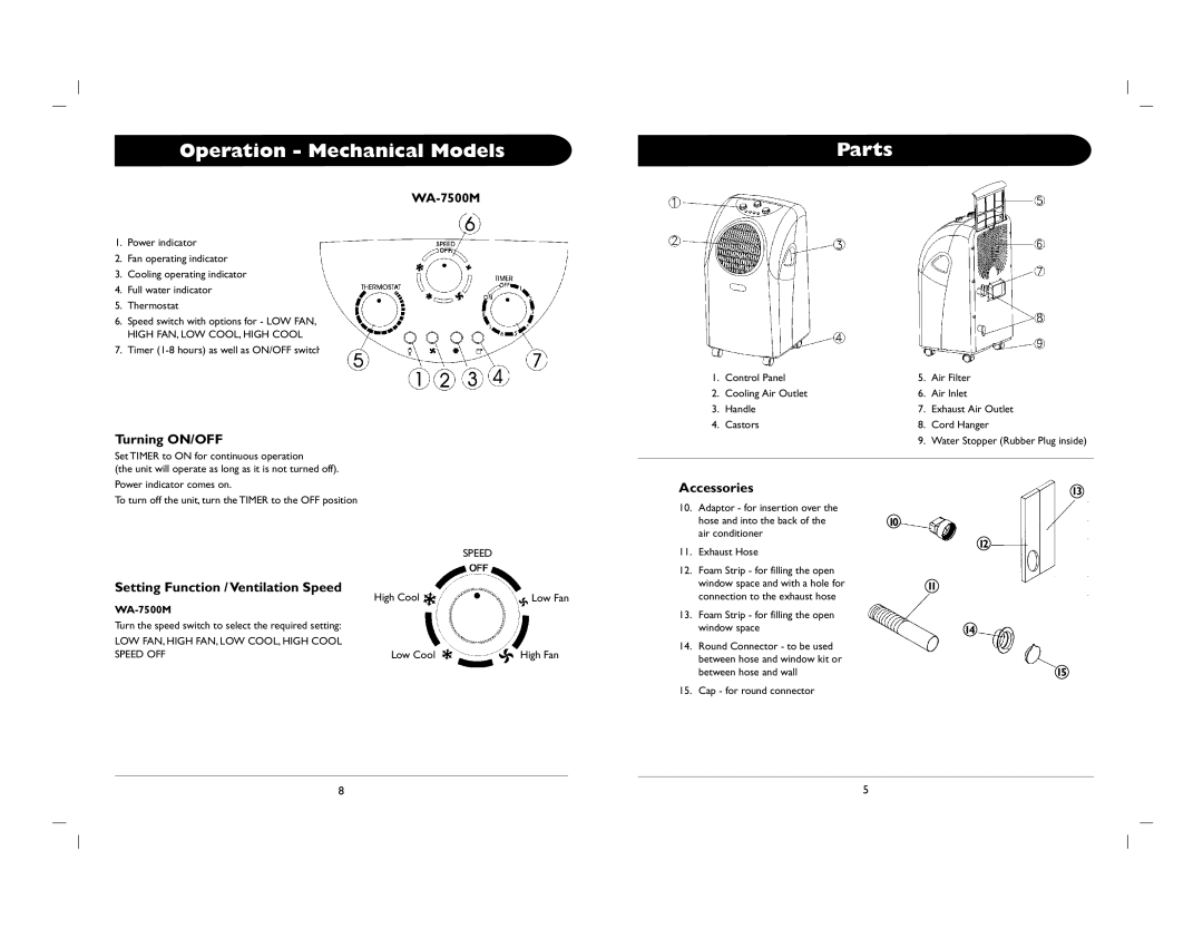
The WA-7500M is equipped with multiple speed settings, allowing users to customize the airflow to their preference. Whether you need a gentle breeze or powerful cooling, this unit provides flexibility to match your comfort needs. The unit also features a large water tank capacity, minimizing the frequency of refills and enabling longer operation times. Conveniently, a water level indicator lets users easily monitor the remaining water and plan refills accordingly.
Portability is another hallmark of the WA-7500M. Designed with caster wheels, this air cooler can be effortlessly moved from room to room. Whether you want it in your living room, bedroom, or office, its lightweight design facilitates easy relocation without hassle. Additionally, the unit operates with minimal noise, allowing it to be used in quiet environments, such as during sleep or meetings.
The WA-7500M includes essential safety features such as an automatic shut-off function to prevent overheating and ensure safe operation. The user-friendly control panel offers easy access to settings and configurations, making it simple for anyone to operate.
In summary, the Sunpentown International WA-7500M is a comprehensive solution for cooling and humidifying indoor spaces. With its efficient design, powerful capabilities, and user-friendly features, it stands out as an impressive option for anyone looking to beat the heat while maintaining energy efficiency.