S-646 specifications
The Sunrise Medical S-646 is a cutting-edge power wheelchair designed to enhance mobility and independence for users with various physical disabilities. This innovative wheelchair features a blend of advanced technology and ergonomic design, making it a popular choice for users seeking comfort and ease of maneuverability.One of the standout features of the S-646 is its robust power base, which is built for stability and durability. The wheelchair is equipped with two powerful motors, ensuring smooth operation on various terrains, including both indoor and outdoor environments. The S-646 can effortlessly navigate tight spaces and transition over obstacles, such as curbs and inclines, thanks to its advanced suspension system.
Comfort is paramount in the design of the S-646. The wheelchair comes with a highly adjustable seating system, including options for tilt, recline, and lateral support. This allows users to customize their seating position for optimal comfort and pressure relief, significantly reducing the risk of pressure sores during prolonged use. The upholstery is designed with breathable materials that provide additional comfort over long periods.
In terms of technology, the S-646 incorporates an intuitive joystick control system, allowing users to easily navigate their surroundings. The joystick is highly responsive and can be adapted for users with varying levels of motor control, ensuring accessibility for everyone. Additionally, the power wheelchair features programmable settings, enabling caregivers and users to personalize the chair's speed and control sensitivity to fit individual needs.
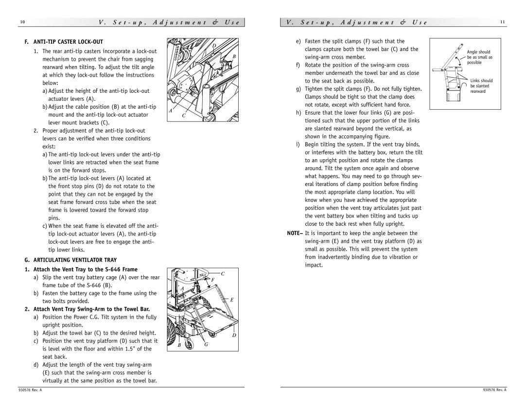
Safety features are also a significant consideration in the design of the S-646. The wheelchair includes anti-tipper technology and stabilizing components that provide added security, particularly when navigating steep slopes. LED lighting ensures visibility during low-light conditions, enhancing overall safety.
The S-646 is designed with portability in mind. It can be disassembled easily into compact components, making transportation and storage hassle-free. Battery longevity is another key characteristic, with options for high-capacity batteries that extend the range of usage, allowing users to travel longer distances without frequent recharging.
In summary, the Sunrise Medical S-646 power wheelchair stands out due to its combination of advanced features, ergonomic design, and innovative technology. Its focus on comfort, safety, and user adaptability makes it an excellent choice for individuals seeking a reliable and functional mobility solution.

