SAS-826A specifications
Super Micro Computer, a well-known player in the server and storage market, introduced the SAS-826A, a high-performance and versatile 2U rackmount server designed to cater to a wide range of enterprise-level applications. The SAS-826A stands out with its robust features, cutting-edge technologies, and impressive characteristics, making it an ideal choice for data centers, cloud computing, and heavy workloads.One of the main features of the SAS-826A is its support for Intel's latest processors, enabling users to leverage powerful performance capabilities. The system can accommodate dual Intel Xeon Scalable processors, providing substantial computational power and scalability to handle demanding tasks effectively. The server supports multiple memory configurations, allowing for up to 3TB of DDR4 memory, delivering enhanced performance for memory-intensive applications.
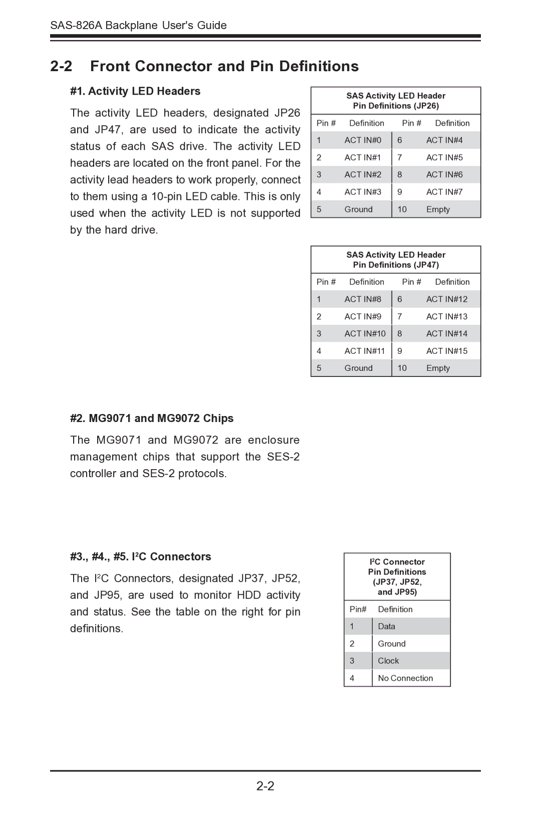
The SAS-826A is equipped with an extensive storage capacity, supporting up to 26 hot-swappable 2.5" SATA or SAS drive bays. This design ensures easy access to drives for maintenance and replacement without necessitating system downtime. The server also supports various types of storage configurations, including RAID options, allowing users to tailor their storage solution to meet their specific requirements for redundancy and performance.
In terms of expandability, the SAS-826A features multiple PCIe slots, enabling the addition of various expansion cards such as GPUs, network adapters, or storage controllers. This flexibility ensures that the server can adapt to evolving technology trends and user needs.
Energy efficiency is another strong point of the SAS-826A, designed with Super Micro's commitment to green computing in mind. The server supports the latest power supply technologies and is optimized for low power consumption without compromising performance. This not only reduces operational costs but also aligns with sustainability goals commonly pursued by businesses today.
Furthermore, the SAS-826A boasts advanced management features, including Supermicro's Intelligent Management Module (IMM), which provides out-of-band management capabilities. Administrators can monitor system performance, perform remote management, and receive alerts for critical events, helping maintain optimal server uptime.
In summary, the Super Micro Computer SAS-826A combines high-performance processing, extensive storage capabilities, and a focus on energy efficiency, making it a compelling solution for enterprises looking to enhance their IT infrastructure. Its flexibility and robust management features make it a wise choice for a variety of applications in today's fast-paced business environments.

