Figure 3. Wiring diagram for the 2100D and 2100TD detector:
+
INITIATING
LOOP
–
EOL RESISTOR SPECIFIED BY PANEL MANUFACTURER
UL LISTED | + |
COMPATIBLE | – |
CONTROL |
|
PANEL |
|
RA400Z
REMOTE
ANNUNCIATOR
+
+
– |
|
+ | + |
– | |
| RA400Z |
| REMOTE |
| ANNUNCIATOR |
OPTIONAL CLASS A WIRING
+
+
–
+
| CAUTION |
| or analog voltmeter to check the detector sensitivity as | ||
|
|
|
| described in the test module’s manual. | |
Dust covers are an effective way to limit the entry of dust | |||||
C. Smoke Entry Test | |||||
into smoke detector sensing chambers. However, they may | |||||
Hold a smoldering punk stick or cotton wick at the side | |||||
not completely prevent airborne dust particles from en- | |||||
of the detector and gently blow smoke through the de- | |||||
tering the detector. Therefore, System Sensor recommends | |||||
tector until the unit alarms. | |||||
the removal of detectors before beginning construction or | |||||
D. Direct Heat Method (Model 2100TD only – Hair dryer of | |||||
other dust producing activity. Be sure to remove dust covers | |||||
from any sensors that were left in place during construction | |||||
Direct the heat toward either of the side thermistors. | |||||
as part of returning the system to service. | |||||
Hold the heat source about 12 inches from the detector | |||||
|
|
|
| ||
Testing | in order to avoid damage to the plastic. The detector will | ||||
reset only after it has had sufficient time to cool and the | |||||
NOTE: Before testing, notify the proper authorities that the | |||||
power source has been momentarily interrupted. | |||||
smoke detector system is undergoing maintenance | |||||
Both smoke and heat detection testing are recommended | |||||
and will temporarily be out of service. Disable the | |||||
for verifying system protection capability. | |||||
zone or system undergoing maintenance to prevent | |||||
| |||||
unwanted alarms. | A detector that fails to activate with any of the above tests | ||||
Detectors must be tested after installation and following | |||||
should first be cleaned as outlined in the MAINTENANCE | |||||
periodic maintenance. Test the 2100D as follows: | |||||
section which follows. If the detector still fails to activate, it | |||||
A. Test Switch | |||||
should be returned for repair. | |||||
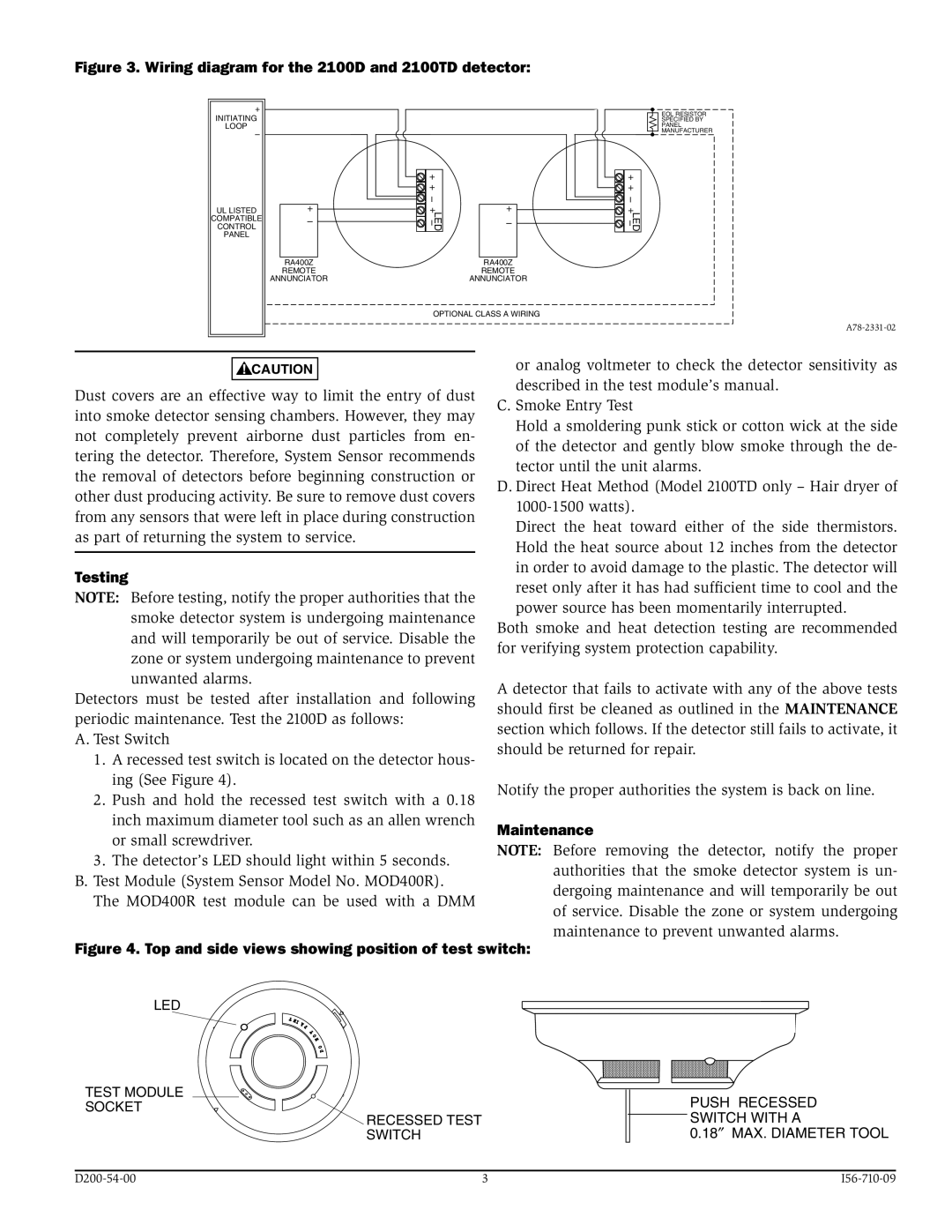
1. A recessed test switch is located on the detector hous- | |||||
| |||||
ing (See Figure 4). | Notify the proper authorities the system is back on line. | ||||
2. Push and hold the recessed test switch with a 0.18 | |||||
| |||||
inch maximum diameter tool such as an allen wrench | Maintenance | ||||
or small screwdriver. | |||||
NOTE: Before removing the detector, notify the proper | |||||
3. The detector’s LED should light within 5 seconds. | |||||
authorities that the smoke detector system is un- | |||||
B. Test Module (System Sensor Model No. MOD400R). | |||||
dergoing maintenance and will temporarily be out | |||||
The MOD400R test module can be used with a DMM | |||||
of service. Disable the zone or system undergoing | |||||
|
|
|
| ||
|
|
|
| maintenance to prevent unwanted alarms. | |
Figure 4. Top and side views showing position of test switch: | |||||
LED |
| ||||
TEST MODULE | PUSH RECESSED | |
SOCKET | ||
SWITCH WITH A | ||
RECESSED TEST | ||
SWITCH | 0.18″ MAX. DIAMETER TOOL |
3 |