Figure 3. Wiring diagram for the 2112/24TSRB detector:
POWER +
TO
DETECTORS
–
| + | P | + | P |
| + | + | ||
| – | W | – | W |
| – | R | – | R |
UL LISTED | N.O. |
| N.O. |
|
CONTROL |
|
|
|
|
PANEL | C |
| C |
|
|
|
| ||
| TRBL |
| TRBL |
|
INITIATING+
LOOP –
OPTIONAL CLASS A WIRING
EOL RESISTOR
SPECIFIED BY
PANEL
MANUFACTURER
![]()
![]() CAUTION
CAUTION
Dust covers are an effective way to limit the entry of dust into smoke detector sensing chambers. However, they may not completely prevent airborne dust particles from en- tering the detector. Therefore, System Sensor recommends the removal of detectors before beginning construction or other dust producing activity. Be sure to remove dust covers from any sensors that were left in place during construction as part of returning the system to service.
Testing
NOTE: Before testing, notify the proper authorities that the smoke detector system is undergoing maintenance and will be temporarily out of service. Disable the zone or system undergoing maintenance to prevent unwanted alarms.
Detectors must be tested after installation and following periodic maintenance. Test the 2112/24TSRB as follows: A. Test Switch
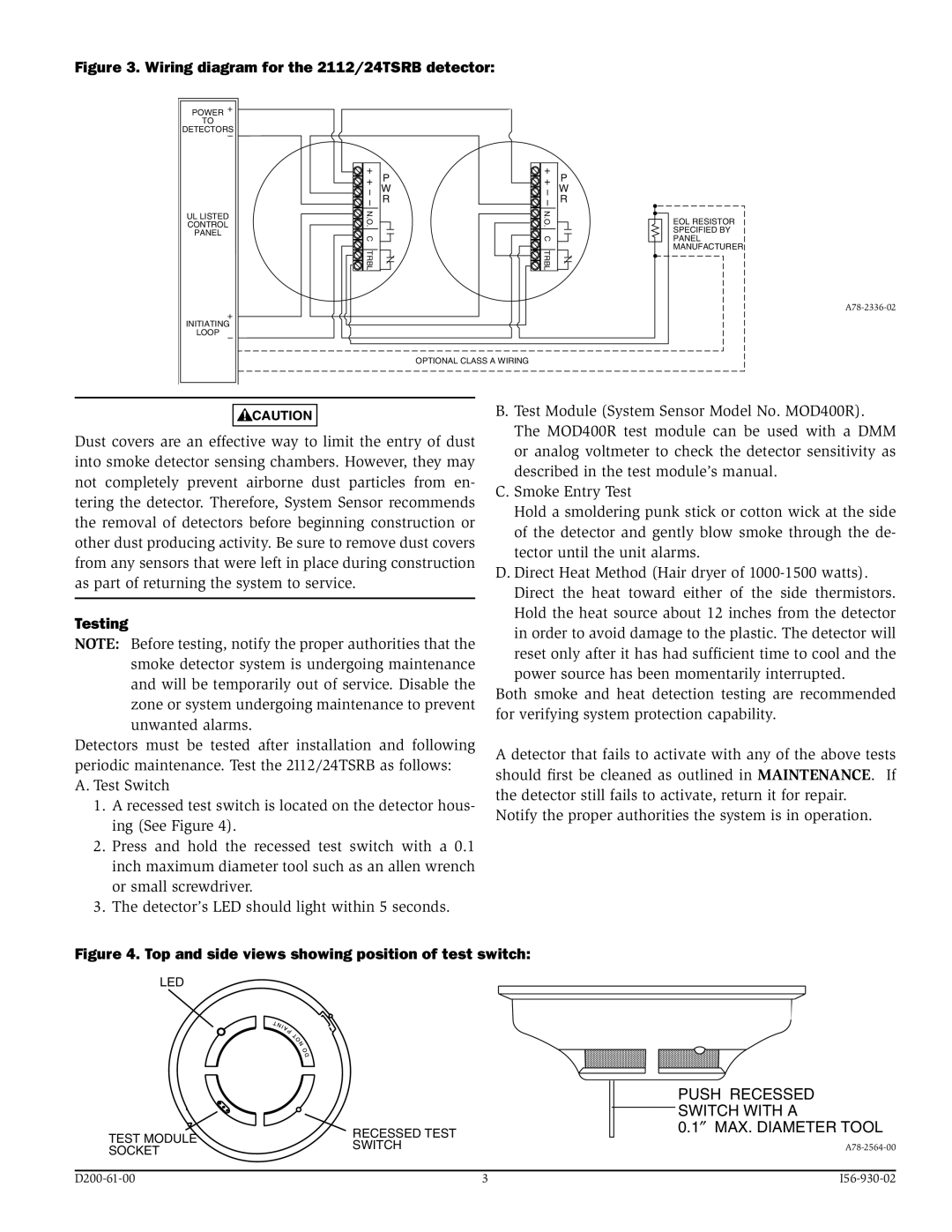
1.A recessed test switch is located on the detector hous- ing (See Figure 4).
2.Press and hold the recessed test switch with a 0.1 inch maximum diameter tool such as an allen wrench or small screwdriver.
3.The detector’s LED should light within 5 seconds.
B. Test Module (System Sensor Model No. MOD400R). The MOD400R test module can be used with a DMM or analog voltmeter to check the detector sensitivity as described in the test module’s manual.
C. Smoke Entry Test
Hold a smoldering punk stick or cotton wick at the side of the detector and gently blow smoke through the de- tector until the unit alarms.
D. Direct Heat Method (Hair dryer of
Both smoke and heat detection testing are recommended for verifying system protection capability.
A detector that fails to activate with any of the above tests should first be cleaned as outlined in MAINTENANCE. If the detector still fails to activate, return it for repair.
Notify the proper authorities the system is in operation.
Figure 4. Top and side views showing position of test switch:
LED
|
| PUSH RECESSED | |
|
| SWITCH WITH A | |
TEST MODULE | RECESSED TEST | 0.1″ | MAX. DIAMETER TOOL |
SWITCH |
| ||
SOCKET |
| ||
|
|
| |
| 3 | ||