INSTALLATION AND MAINTENANCE INSTRUCTIONS
|
| 3825 Ohio Avenue, St. Charles, Illinois 60174 |
M500S Supervised Control Module | ||
www.systemsensor.com | ||
Specifications |
|
|
Normal Operating Voltage: | 15 to 32 VDC |
|
Maximum Current Draw: | 6.5mA (LED On) |
|
Operating Current: | 350 µA max., 1 communication every 5 seconds 47k EOL resistor; 485 µA max. (Communicating, NAC Shorted) | |
Maximum NAC Line Loss: | 4 VDC |
|
External Supply Voltage (between Terminals T10 and T11) |
| |
Maximum (NAC): | Regulated 24VDC |
|
Maximum (Speakers): | 70.07 V RMS, 50 W |
|
Max. NAC Current Ratings: | For class B wiring system, the current rating is 3A; For class A wiring system, the current rating is 2A | |
Temperature Range: | 32˚F to 120˚F (0˚C to 49˚C) |
|
Humidity: | 10% to 93% |
|
Dimensions: | 41/2˝ H × 4˝ W × 11/4˝ D (Mounts to a 4˝ square by 21/8˝ deep box.) |
|
Accessories: | SMB500 Electrical Box; CB500 Barrier |
|
Before Installing
This information is included as a quick reference installation guide. Refer to the control panel installation manual for detailed system information. If the modules will be installed in an existing operational system, inform the opera- tor and local authority that the system will be temporarily out of service. Dis- connect power to the control panel before installing the modules.
NOTICE: This manual should be left with the owner/user of this equipment.
General Description
M500S Supervised Control Modules are intended for use in intelligent, two- wire systems, where the individual address of each module is selected using the
Compatibility Requirements
To ensure proper operation, these modules shall be connected to listed com- patible system control panels only.
Figure 1. Controls and indicators:
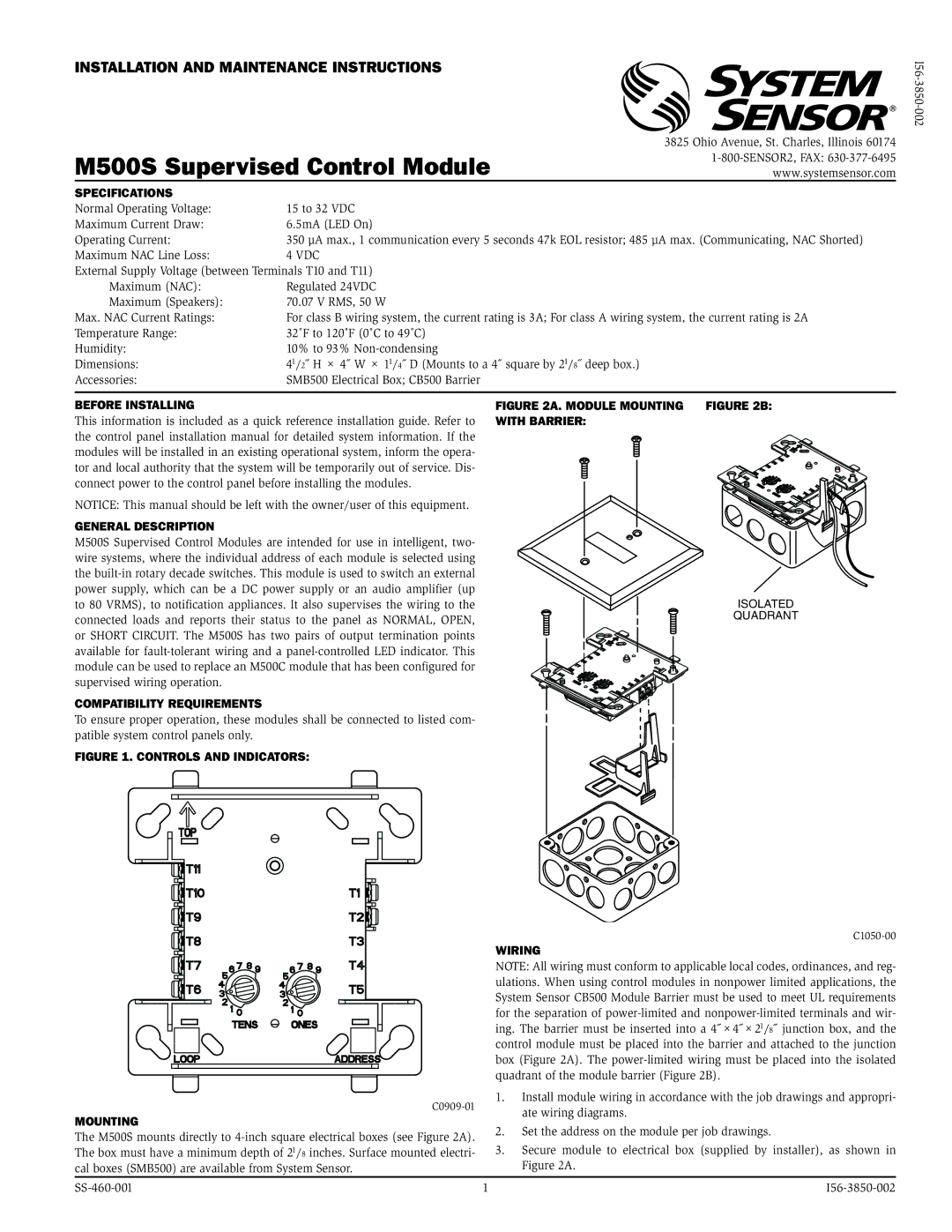
Figure 2A. Module mounting Figure 2B: with barrier:
ISOLATED
QUADRANT
Wiring
NOTE: All wiring must conform to applicable local codes, ordinances, and reg- ulations. When using control modules in nonpower limited applications, the System Sensor CB500 Module Barrier must be used to meet UL requirements for the separation of
1. | Install module wiring in accordance with the job drawings and appropri- | ||
| ate wiring diagrams. | ||
Mounting |
| ||
2. | Set the address on the module per job drawings. | ||
The M500S mounts directly to | |||
3. | Secure module to electrical box (supplied by installer), as shown in | ||
The box must have a minimum depth of 21/8 inches. Surface mounted electri- | |||
cal boxes (SMB500) are available from System Sensor. |
| Figure 2A. | |
1 |