TRIVIEW | Pole Mount Kit | |
|
| Installation Instruction |
WARNING | Because pole situation vary from job to job, it is mandatory that you consult with the appropriate local | |
loads. Pole must be made of metal material and applicable pole diameter is 1.5 ~ 2.0 inch. Maximum | ||
| engineer and architect to ensure that the mounting brackets are properly mounted to handle the applied | |
load 16 lb.,![]()
![]() m
m![]()
![]() oni
oni![]()
![]() t
t![]() or
or ![]() -1503
-1503![]() ,
,![]()
![]() -1
-1![]()
![]() nd
nd ![]()
![]() -170
-170![]()
![]() 3
3![]() rec
rec![]() omme
omme![]() nd
nd![]() e
e![]() d.
d.![]() Do no
Do no![]()
![]() t use
t use ![]() over
over![]()
![]() for
for![]()
![]() ce
ce![]() on
on![]() t
t![]() he sc
he sc![]() re
re![]() ws
ws![]()
![]() durin
durin![]() g
g![]()
![]() in
in![]()
![]() st
st![]() al
al![]()
![]() l
l![]() ation.
ation.
THIS MOUNT KIT USED FOR LCD MONITOR |
|
|
|
THAT VESA STANDARD IS 75MM. |
|
|
|
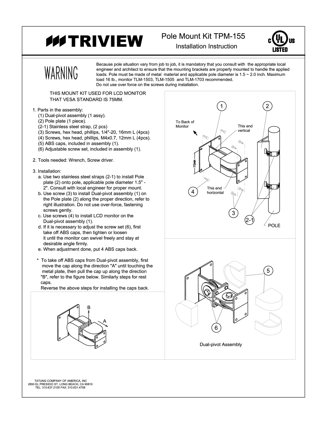
1. Parts in the assembly: |
| 1 | 2 |
|
|
| |
(1) |
|
|
|
(2) Pole plate (1 piece). | To Back of |
|
|
Monitor | This end |
| |
(3) Screws, hex head, phillips, |
| vertical |
|
|
|
| |
(4) Screws, hex head, phillips, M4x0.7, 12mm L (4pcs). |
|
|
|
(5) ABS caps, included in assembly (1). |
|
|
|
(6) Adjustable screw set, included in assembly (1). |
|
|
|
2. Tools needed: Wrench, Screw driver. | 75MM |
|
|
|
|
| |
3. Installation: |
|
|
|
a. Use two stainless steel straps |
|
|
|
plate (2) onto pole, applicable pole diameter 1.5" - |
|
|
|
2". Consult with local engineer for proper mount. | 4 | This end |
|
b. Use screw (3) to install | horizontal |
| |
|
|
| |
the Pole plate (2) along the proper direction, refer to |
|
|
|
right illustration. Do not use |
|
|
|
screws gently. |
| 3 |
|
c. Use screws (4) to install LCD monitor on the |
|
| |
|
| ||
|
| ||
|
| POLE | |
d. If it is necessary to adjust the screw set (6), first |
|
| |
|
|
| |
take off ABS caps, then tighten or loosen |
|
|
|
it until the monitor can swivel freely and stay at |
|
|
|
desirable angle firmly. |
|
|
|
e. When adjustment done, put 4 ABS caps back. |
|
|
|
* To take off ABS caps from |
|
|
|
move the cap along the direction "A" until touching the |
|
|
|
metal plate, then pull the cap up along the direction |
|
| 5 |
"B", refer to the figure below. Similarly steps for rest |
|
|
|
caps. |
|
|
|
Reverse the above steps for installing the caps back. |
|
|
|
B |
|
|
|
A |
|
|
|
|
| 6 |
|
|
|
|
TATUNG COMPANY OF AMERICA,![]()
![]() IN
IN![]() C 28
C 28![]() 5
5![]() 0 EL PRESIDIO ST,
0 EL PRESIDIO ST,![]() LONG BEACH,
LONG BEACH,![]() CA
CA ![]() 90810
90810
TEL: 3![]() 10.637.2105 FAX:
10.637.2105 FAX: ![]() 310.631.4758
310.631.4758
