Advance Data Sheet: Dualeta™ iQA Series – Dual Quarter Brick
Remote On/Off
The power modules have an internal remote On/Off circuit. The user must supply an
The standard on/off logic is positive logic. The power module will turn on if the On/Off is left open and will be off if the On/Off is connected to Vin
An optional negative logic is available. The power module will turn on if the On/Off terminal is connected to Vin
Two trim configurations are offered on the
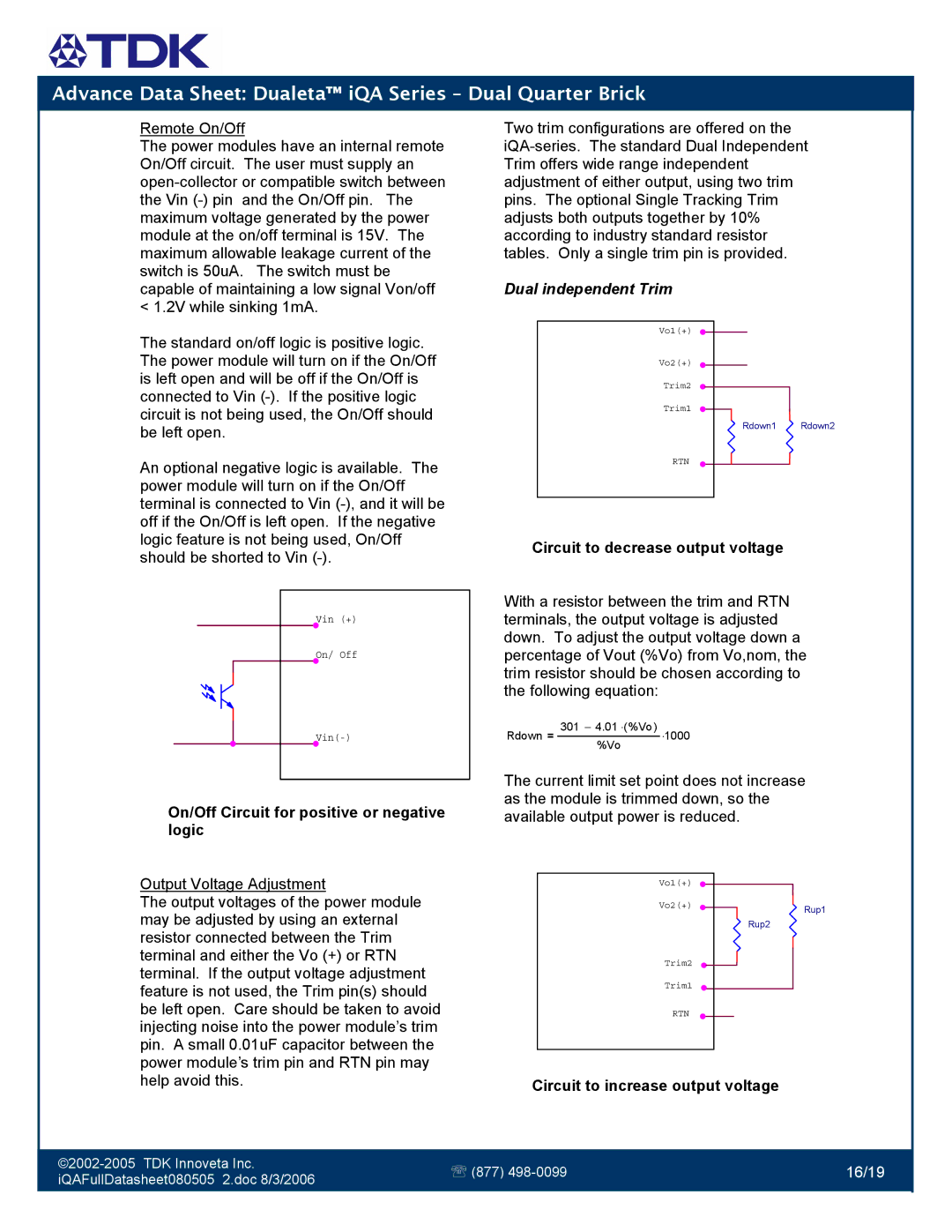
Dual independent Trim
Vo1(+)
Vo2(+)
Trim2
Trim1
Rdown1 Rdown2
RTN
Circuit to decrease output voltage
Vin | (+) |
On/ | Off |
On/Off Circuit for positive or negative logic
Output Voltage Adjustment
The output voltages of the power module may be adjusted by using an external resistor connected between the Trim terminal and either the Vo (+) or RTN terminal. If the output voltage adjustment feature is not used, the Trim pin(s) should be left open. Care should be taken to avoid injecting noise into the power module’s trim pin. A small 0.01uF capacitor between the power module’s trim pin and RTN pin may help avoid this.
With a resistor between the trim and RTN terminals, the output voltage is adjusted down. To adjust the output voltage down a percentage of Vout (%Vo) from Vo,nom, the trim resistor should be chosen according to the following equation:
Rdown = 301 − 4.01 ⋅(%Vo) ⋅1000 %Vo
The current limit set point does not increase as the module is trimmed down, so the available output power is reduced.
Vo1(+) |
|
Vo2(+) | Rup1 |
| |
| Rup2 |
Trim2
Trim1
RTN
Circuit to increase output voltage
℡ (877) | 16/19 | ||
iQAFullDatasheet080505 2.doc 8/3/2006 | |||
|
| ||
|
|
|