TIPS FOR USING THE SPEAKERPHONE
1)Face the telephone to talk (the microphone is located on the front edge of the telephone).
2)To go to handset mode, lift the handset, the SPEAKERPHONE will automatically go off. To return to speaker mode, press the SPEAKERPHONE key, the LED will light. Replace the handset (hang up).
3)To end a speakerphone call, press the SPEAKERPHONE key.
ADJUSTING SPEAKERPHONE VOLUME
To increase/decrease speakerphone volume:
1)Locate the slide switch (labeled SPKER VOL) on the right side of the telephone.
2)To increase speaker volume, slide the SPKR VOL switch back towards the rear of the telephone. To decrease speaker volume, slide the SPKR VOL switch forward towards the front of the telephone.
RMA PROCEDURES
The following procedure should be followed with all Teledex telephone products prior to sending the telephone to the factory for repair.
1)Please perform the tests listed below:
a.Test the telephone on a different telephone jack.
b.Test telephone with a different line cord.
c.Test with a different handset cord (coiled cord).
d.For two line products, please ensure that one of the line buttons is pressed (if both line buttons are in the UP position, the telephone will not operate).
2)If the steps listed above do not provide a remedy for the suspect telephone, please place a tag on the individual telephone describing the defect. Next, call the Teledex Repair Department at 1 (800)
3)Kindly note: An RMA number is unique to each return shipment. Do not duplicate this number on any future shipments.
SHIPPING INSTRUCTIONS:
Please print the RMA number clearly on the outside of your shipping carton(s). Please ship to the following address:
Teledex LLC / RMA#___________
6311 San Ignacio Avenue
San Jose, CA 95119
FREIGHT CHARGES:
The Customer is responsible for shipping products for repair to Teledex. After repair, Teledex will return telephone products to the Customer freight prepaid in the same manner in which is was sent (i.e. Freight sent to Teledex UPS Blue, will be returned via 2 day ship- ping).
**Please note: When telephones are returned for repair due to misuse (i.e. liquid spills, abuse, or Customer modification - warranty label broken), the Customer will be charged the standard repair fee, regard- less of warranty status.
CONVERTING FROM DESK TO WALL MOUNT
2)Rotate the clip a half turn (180 degrees) so that the side with the protruding edge is towards the top. This edge will hold the handset. (Closest to the hookswitch.)
3)Return the clip to its original location by pushing the clip dow wards, until it stops (snaps into place).
4)Turn the BTX4550 over so that the back side is up, facing you (A non abrasive surface is suggested to prevent scratching).
5)Locate and remove the mounting bracket, firmly push back and pull up to remove two of the four retaining tabs.
6)Rotate the mounting bracket a half turn (180 degrees) so that the mounting eyelet is facing in the same direction as the other mounting eyelet located on the telephone.
7)Insert the top two retaining tabs of the mounting brackets into the mounting bracket slots (located near the middle of the tele- phone). Then firmly push down to insert the retaining tabs on the opposite side of the mounting bracket.
8)Connect a short modular line cord into the jack on the back of the phone (labeled TO TEL). Route the line cord through the line cord channel. Connect the other end of line cord to the phone jack on the wall mounting plate.
9)Turn the telephone over, and slide the BTX4550 down onto the wall plate mounting posts. Both eyelets should line up with the mounting posts (When properly installed the telephone will be stable and secure).
10)Complete the wall mounting by installing the handset and hand set cord.
REQUIREMENTS OF PART 68 - FCC RULES
This device has been granted a registration number by the Federal Communications Commission, under Part 68 rules and regulations for direct connection to the telephone lines. In order to comply with these FCC rules, the following instructions must be carefully read and applicable portions fol- lowed completely:
1.Direct connection to the telephone lines may be made only through the standard modular cord fur- nished, to the utility installed jack. No connection may be made to party or coin phone lines. On the bottom of the phone is a label that contains among other information, the FCC Registration Number and the Ringer Equivalence number (REN) for this equipment. If requested this informa- tion must be provided to the telephone company. The USOC Jack for this equipment is RJ11C.
2.The telephone company, under certain circumstances, may temporarily discontinue and make changes in facilities and services which may affect the operation of the users' equipment: howev- er, the user shall be given adequate notice in writing to allow the user to maintain uninterrupted service.
3.In certain circumstances, it may be necessary for the telephone company to request information from you concerning the equipment which you have connected to your telephone line. Upon request of the telephone company, provide the FCC registration number and the ringer equiva- lence number of the equipment which is connected to your line; this information will be found on the device.
4.If any of your telephone equipment is not operating properly, you should immediately remove it from the telephone line. It may cause harm to the telephone network.
5.If the telephone company notes a problem, they may temporarily discontinue service. When prac- tical, they will notify you in advance of disconnection. If advance notice is not feasible, the tele- phone company must; promptly notify you of such temporary discontinuance; afford the opportuni- ty to correct the condition; inform you of your rights to bring a complaint to the FCC under their rules.
6.Repairs to the device may be made only by the manufacturer or an authorized service agency. This applies at any time during and after warranty. If unauthorized repair is performed, registration, connection to the telephone lines and remainder of warranty period all become null and void.
7.This equipment is hearing aid compatible.
REQUIREMENTS OF PART 15 - FCC RULES
NOTE: This equipment has been tested and found to comply with the limits for a Class B digital device, pursuant to Part 15 of the FCC Rules. These limits are designed to provide reasonable pro- tection against harmful interference in a residential installation. This equipment generates, uses, and can radiate radio frequency energy and, if not installed and used in accordance with the instruction, may cause harmful interference to radio communications. However, there is not a guarantee that interference will not occur in a particular installation. If this equipment does cause harmful interfer- ence to radio or television reception, which can be determined by turning the equipment off and on, the user is encouraged to try to correct the interference by one or more of the following measures: - Move the telephone away from the receiver.
INDUSTRY OF CANADA REQUIREMENTS
Notice: The Industry Canada label identifies certified equipment. This certification means that the equipment meets certain telecommunications network protective operational and safety requirements as prescribed in the appropriate Terminal Equipment Technical Requirements documents. The department does not guarantee the equipment will operate to the users satisfaction.
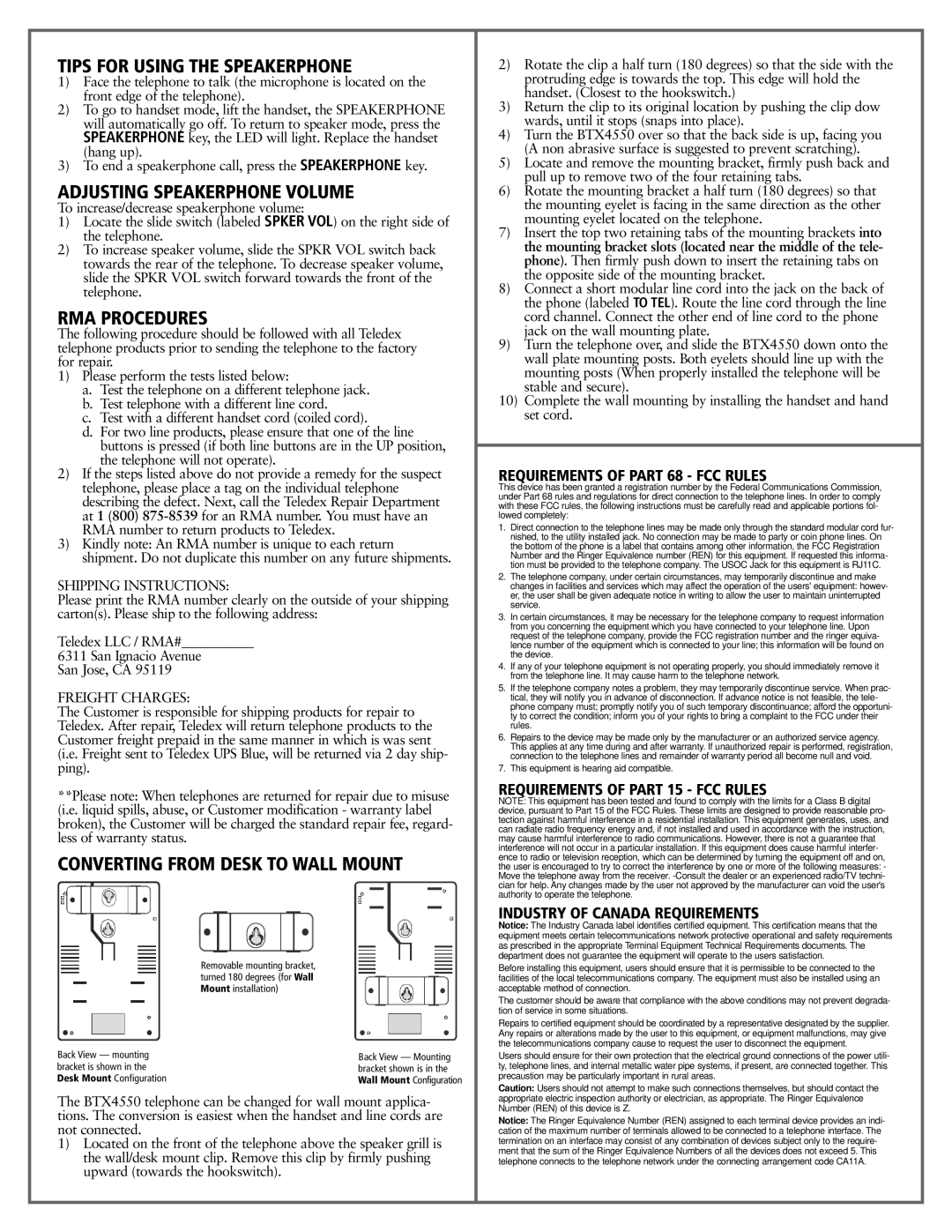
Back View — mounting bracket is shown in the Desk Mount Configuration
Removable mounting bracket, turned 180 degrees (for Wall Mount installation)
Back View — Mounting bracket shown is in the Wall Mount Configuration
Before installing this equipment, users should ensure that it is permissible to be connected to the facilities of the local telecommunications company. The equipment must also be installed using an acceptable method of connection.
The customer should be aware that compliance with the above conditions may not prevent degrada- tion of service in some situations.
Repairs to certified equipment should be coordinated by a representative designated by the supplier. Any repairs or alterations made by the user to this equipment, or equipment malfunctions, may give the telecommunications company cause to request the user to disconnect the equipment.
Users should ensure for their own protection that the electrical ground connections of the power utili- ty, telephone lines, and internal metallic water pipe systems, if present, are connected together. This precaustion may be particularly important in rural areas.
Caution: Users should not attempt to make such connections themselves, but should contact the
The BTX4550 telephone can be changed for wall mount applica- tions. The conversion is easiest when the handset and line cords are not connected.
1)Located on the front of the telephone above the speaker grill is the wall/desk mount clip. Remove this clip by firmly pushing upward (towards the hookswitch).
appropriate electric inspection authority or electrician, as appropriate. The Ringer Equivalence Number (REN) of this device is Z.
Notice: The Ringer Equivalence Number (REN) assigned to each terminal device provides an indi- cation of the maximum number of terminals allowed to be connected to a telephone interface. The termination on an interface may consist of any combination of devices subject only to the require- ment that the sum of the Ringer Equivalence Numbers of all the devices does not exceed 5. This telephone connects to the telephone network under the connecting arrangement code CA11A.